Component Instantiation
Formal Definition
A component instantiation
statement defines a subcomponent of the design entity in which it
appears, associates signals or values with the ports of that
subcomponent, and associates values with generics of that subcomponent.
Simplified Syntax
label : [ component ] component_name
generic
map ( generic_association_list )
port
map ( port_association_list );
label : entity entity_name [(architecture_identifier)]
generic
map ( generic_association_list )
port
map ( port_association_list );
label : configuration configuration_name
generic
map ( generic_association_list )
port
map ( port_association_list );
Description
A component represents an entity/architecture pair. It specifies a
subsystem, which can be instantiated
in another architecture, leading to a hierarchical
specification. Component instantiation is like plugging a hardware
component into a socket in a board (Fig. 1 in Example 1).
The component instantiation statement introduces a subsystem declared
elsewhere, either as a component or as an entity/architecture pair
(without declaring it as a component).
The component instantiation contains a reference to the instantiated
unit and actual values for generics and ports. There are three forms
of component instantiation:
-
instantiation of a component;
-
instantiation of a design entity;
-
instantiation of a configuration;
See configuration for
details on the third form.
The actual values of generic map aspect and port map aspect
connections allow assigning the components of the actual values to
generic parameters and ports.
INSTANTIATION OF A COMPONENT
Instantiation of a component introduces a relationship to a unit
defined earlier as a component (see component
declaration). The name of the instantiated component must
match the name of the declared component. The instantiated component
is called with the actual parameters for generics and ports. The
association list can be either positional
or named.
In the positional association
list, the actual parameters (generics and ports) are connected in
the same order in which ports were declared in the component (Example 1).
Named association allows to list the generics and ports in an order
that is different from the one declared for the component. In such a
case the ports have to be explicitly referenced (Example 2).
INSTANTIATION OF A DESIGN ENTITY
It is not necessary to define a component to instantiate it: the
entity/architecture pair can be instantiated directly. In such a
direct instantiation, the component instantiation statement contains
the design entity name and optionally the name of the architecture to
be used for this design entity. The reserved word entity
follows the declaration of this type of the component instantiation
statement (Example 3).
If architecture name is not specified in an instantiation of a design
entity, the last compiled architecture associated with the entity
will be taken.
Examples
Example 1
architecture Structural of
ALU is
signal X,Y,S,C : bit;
component HalfAdder is
port
(In1, In2 : in bit;
Sum,
Carry : out bit);
end component HalfAdder;
begin
HA : HalfAdder port map (X,Y,S,C);
.
. .
end architecture Structural;
The structural specification of an arithmetic-logic unit ALU uses an
instantiation of a HalfAdder component. Note that the component is
instantiated with signals of the ALU system. The signals are
associated positionally.
Example 2
architecture Structural of
ALU is
signal X,Y,S,C : bit;
component HalfAdder is
port (In1,
In2 : in bit;
Sum, Carry : out bit);
end component HalfAdder;
begin
HA :
HalfAdder port map
(Sum=>S, Carry=>C,
In1=>X, In2=>Y);
. . .
end architecture Structural;
This structural architecture performs the same function as in the Example
1. The only difference lies in the way the association list
is specified for the component ports - the signals are associated
with named association.
Example 3
entity XOR_GATE_4 is
port(IN1,IN2:
in BIT_VECTOR(0 to 3);
OUT1 : out
BIT_VECTOR(0 to 3));
end entity XOR_GATE_4;
architecture XOR_BODY_4 of
XOR_GATE_4 is
begin
OUT1 <=
IN1 xor IN2 after
5 ns;
end architecture XOR_BODY_4;
entity EXAMPLE is
end entity EXAMPLE;
architecture STRUCTURE_1 of
EXAMPLE is
signal S1,S2 : BIT_VECTOR(0 to 3);
signal S3 : BIT_VECTOR(0 to 3);
begin
X1 : entity WORK.XOR_GATE_4(XOR_BODY_4)
port map (S1,S2,S3);
end architecture STRUCTURE_1;
Entity XOR_GATE_4 is directly instantiated here, without declaring a
component. The architecture, which specifies the body of the entity
XOR_GATE_4 is called XOR_BODY_4 and is supported in parentheses.
Further specification is similar to the one in instantiation of a
component. The entity and architecture instantiated here must be
located in the WORK library prior to this instantiation.
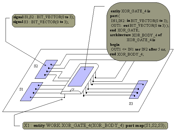
Figure 1. Example of a direct instantiation.
Important Notes
|

