![]()
![]()
![]()
Next:5. Design-for-Test Tools Up: Appnotes Index Previous:3. Hardware/Software Co-Design Tools
The major CAD tools for the RASSP Baseline 2 system are shown in Figure 4.1-1.
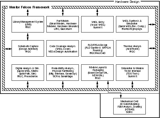
Figure 4.1-1. RASSP hardware design tools.
The major inputs to the hardware design process are:
Architecture design defines the top-level hardware architecture and the major elements that go into the detailed design process. The main objective of the detailed design process is to transform the architectural description of the design into the detailed hardware and software components that will be developed, manufactured, and integrated into a prototype processor. As with the prior processes, both hardware and software are verified via a set of detailed functional and performance simulations. When that process is completed, a fully verified virtual prototype of the system exists. The design is first partitioned from the behavioral-level to the appropriate level for all necessary components. Partitioning is driven by component requirements from the Architecture process, with a heavy predisposition toward using library-based components and synthesis of chip and board-level components from the component libraries. Where at all possible, off-the-shelf modules, MCMs, ASICs, chassis and backplanes will be used. The detailed hardware design process may be invoked at any time during the architectural verification process in order to provide more accurate simulation models for high-risk portions of the design. At the end of the architecture selection process (VP2), some portions of the design may already exist as detailed designs. The overall hardware design process is divided into several distinct, yet interrelated subprocesses:
These subprocesses proceed in parallel, each providing information to the others. The steps used to develop detailed hardware implementations are as follows:
The hardware design process transforms the architecture component VHDL models into detailed hardware designs. Abstract, non-evaluated architecture component models are decomposed into full-functional VHDL models of their constituent entities. In addition to the full-functional models, bus-functional models are created where needed to efficiently test interface designs. VHDL structural models are created for the VHDL behavioral models that were developed during the architecture design process. These structural models show the partitioning and interconnection of architecture component modules. Each module is, in turn, further decomposed and partitioned into other modules, macro-cells, MCMs, ASICs, or COTS components. The hierarchical modeling procedure is applied until an entity's constituent units can be either automatically synthesized, obtained from a library either from a previous design, or obtained from a Commercial-Off-The-Shelf library. During the partitioning process, some of the modules, MCMs, and ASICs can be identified as custom parts, while others are selected from COTS parts. For custom-developed parts, VHDL models are developed down to the RTL level, with a fully functional behavior and bus-functional model describing each ASIC. For COTS parts, only VHDL behavioral models are developed or obtained. The VHDL behavioral models describe the timing and functionality of the module, macro-cell, MCM, and/or ASIC.
The test benches developed during the Architecture design process provide the test procedures, stimuli, and expected results to verify that the design meets system requirements. The test benches are executed with the behavioral models of the hardware designs during simulation. The full-functional behavioral model forms the executable specification for a hardware design. We back-annotate the simulation results of the detailed hardware models to the higher level architecture models. A gate-level VHDL description of the design can also be generated and simulated with the test bench. The results of this simulation can be compared with the results of the pre-synthesis simulation to verify that the implementation is correct.
The RASSP Hardware Design toolset includes:
Design Architect is a comprehensive and integrated system for specifying and creating electronic designs at the abstract architectural, detailed logic and circuit levels. As Figure 4.2-1 indicates, Design Architect is the center of activity for most hardware design processes. It lets you create and edit logical designs that are used by downstream processes such as digital simulation and PCB layout. These applications return design information to Design Architect in the form of back annotation values.
Design Architect is a multi-level design environment that includes: a Schematic Editor, a Symbol Editor, and a VHDL Editor. In a multi-level design environment you can:
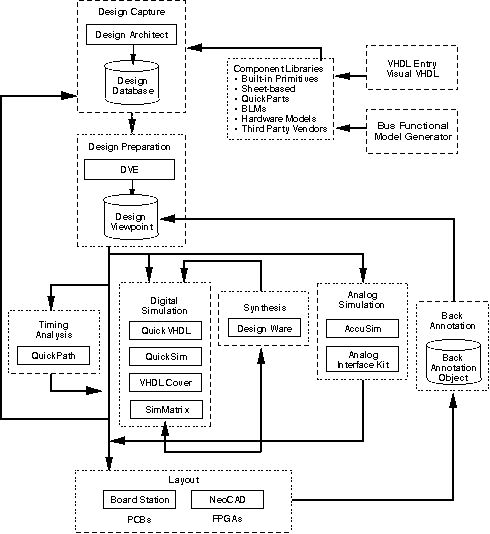
Figure 4.2-1. Mentor IDEA EDA tool set.
See Figure 4.2-2 for a typical Design Architect display.
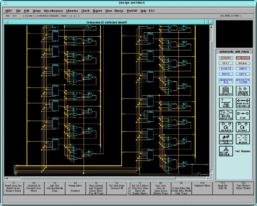
Figure 4.2-2. Design architect screen.
QuickVHDL allows you to quickly model and test a system at a high level of abstraction. This ability means that you can limit the amount t of information that is analyzed at one time to a manageable level. You can also identify and correct many problems before they propagate to the lower gate-level implementations or the breadboard stage. QuickVHDL has the following features:
Mentor Graphics component libraries contain a variety of model types, used to describe the behavior of a circuit. The behavioral description of a circuit is necessary to simulate and analyze the circuit's functionality. The behavioral description of a circuit is defined with a functional model. Some examples of functional models are: schematic models, hardware models, Behavioral Language Models, and VHDL models. The designer selects component models from a wide variety of component libraries, and then places and connects these components together to form schematics and simulation models.
In order to capture designs and prepare them for layout in the LMS environment, the following tools and utilities are used:
PLD Synthesis II is a complete, universal programmable logic device development tool. It supports the following:
Integration with the Mentor environment provides the ability to export schematics to PLD Synthesis II, to provide automatic simulation modeling that can be exported to QuickSim II for module simulation, and support hierarchical design integration where elements at the top level of a design can be schematic, VHDL, behavioral language, or netlist.
QuickPath is a static timing analysis tool which verifies circuit timing by adding up propagation delays along paths between clocked elements in a circuit. This method checks the sums against the specified timing constraints for each circuit path and reports any existing timing violations. QuickPath is a graphical timing analysis tool that reports timing violations on all circuit paths. QuickPath prevents false error reporting by allowing the user to remove "uninteresting" paths from an analysis. In QuickPath, a designer can strategically disable the component pins that these paths pass through and cause the paths to be ignored during an analysis session. In addition, a designer can limit the analysis on several parameters and block uninteresting or invalid paths to reduce analysis time and thus avoid unwanted analysis results. QuickPath does not require stimulus vectors or models that describe the functional behavior of a component but performs an analysis by using pin-to-pin timing information. Timing information can be assigned to any component in the design, or it can be assigned hierarchically to a logical block of the design to reduce the level of analysis QuickPath performs and therefore speed the analysis process. As shown in Figure 4.2-1, QuickPath is integrated with other IDEA Series tools that are used in the design creation and analysis process.
QuickPath is used to perform worst-case static minimum/maximum (min/max) timing analysis on a design. Input signal arrival times and clock information can be specified for the circuit. The clock information includes the clock period, number of clock phases, the clock edge times, and any clock skews. QuickPath uses this information to correctly identify the worst-case clock and signal relationships for accurate verification of circuit timing. In addition, QuickPath determines worst-case paths by using the correct combination of fast and slow components in clock and data paths and considers special circuit conditions (such as the occurrence of common ambiguity) during the analysis process.
Graphics windows display views of schematic sheets and specific paths within the circuit. The selection of an item highlights it within all windows in which it appears, in order to easily locate and view problematic circuit elements within a path or schematic sheet.
Board Designer provides full design, documentation, and manufacturing capabilities for printed circuit board (PCB) designs. Figure 4.2-3 shows the workflow through the PCB products. There are five main PCB tools and libraries:
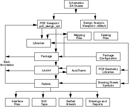
Figure 4.2-3. Board designer process flow.
AutoTherm is an interactive, finite-element based software tool that performs thermal analysis of printed circuit board assemblies. AutoTherm operates within the Mentor Graphics Common User Interface (CUI) environment. The CUI brings a common look and feel to Mentor Graphics applications. AutoTherm uses a single view display. AutoTherm features and capabilities provide ways to improve a printed circuit board design. Within a PCB, AutoTherm models steady-state and transient heat transfer in the following modes:
AutoTherm also allows you to model non-viscous fluid flow, which can be used for analyzing flow velocities for forced convection problems. In a few easy steps, you can accurately:
MCM Station supports multichip module design with integrated high-speed layout tools and advanced packaging techniques and crosstalk analysis.
The Synopsys tools provide an environment for compiling and simulating descriptions written in VHDL. They provide capabilities for source-level debugging, displaying the results of simulations, and performing analysis on these simulation results. It also provides interfaces to C-language models, the LMG SmartModels Library, DesignWare Libraries and Zycad XP Accelerators.
The VHDL Compiler converts VHDL source code to an internal format used by the Synopsys Design Compiler. VHDL Compiler performs two functions: translating VHDL to an internal format, and optimizing the block level representation through various optimization methods.
The Design Compiler reads the design from VHDL Compiler, then optimizes and maps the design's logical structure for a specific ASIC technology library. The user determines how much of the design will be restructured by Design Compiler. The design hierarchy can be left intact, modules can be combined, or the entire design can be compressed into one module. In Design Compiler, the design can be written out in a variety of formats, including VHDL. Existing gate-level netlists, sets of logic equations, or technology-specific circuits can be automatically converted to a VHDL description. The new VHDL description can serve as documentation of the original design. Furthermore, it can be used as a starting point for reimplementation into a new technology. In addition, the VHDL description can be input to a VHDL simulator to provide circuit timing information.
DesignWare Developer, part of the DesignWare product family, lets you create DesignWare components from your own design data. The DesignWare family of products includes tools for a design reuse strategy that leverages the capabilities of Synopsys synthesis, simulation, and test and supports the Model Year Architecture methodology of the RASSP program. DesignWare components are verified design units that have been provided with hooks for integration into the Synopsys synthesis environment.
A DesignWare component consists of verified, synthesizable design description(s). The style of description can vary from a technology-specific netlist or hard macro that will not be altered by synthesis, up to a full hierarchical HDL description of a parametrizable, optimizable design. One of the main advantages of DesignWare is that many different design descriptions (different implementations) can be created for a given function; the designers can let the synthesis tools choose which implementation to use in any given context. Modeling directives applied to the design descriptions control how Design Compiler models the designs during implementation selection. To characterize the implementations for comparison, the synthesis tool creates a preoptimized model for each implementation in the target technology. The timing and area characteristics of the models serve as the basis for implementation selection. The chosen implementation is inserted, by default, as a level of hierarchy in the user's design, which is then mapped to the target technology and optimized. Compilation directives control how (and whether) Design Compiler optimizes the DesignWare component during the optimization of circuits that contain the component. Licensing directives protect the designs from unauthorized use.
When a designer includes an instance of a DesignWare component in a circuit, the component undergoes a chain of transformations when the circuit is synthesized. The process starts with a simple HDL construct--an operator or a component instantiation--supplied by the designer. The final result depends on the nature of implementation the tools select as the best: for synthesizable HDL, the result is an optimized netlist in a particular technology; for a macro, the result is simply an instance of the macro. Design Compiler includes FPGA compiler which provides features intended for high-performance FPGA implementation. The FPGA Compiler supports FPGA-specific optimizations. For Xilinx 4000 series designs, FPGA Compiler supports CLB and IOB cell optimization. The Design Compiler family of products read in and optimize designs in a variety of design formats. These designs can be hierarchical or flat, combinational or sequential. After a design is read in, Design Compiler can optimize it for timing, area, and power (for ECL designs), then mapped it to a target (cell) library. The ECL Compiler supports ECL-specific optimizations, such as creating wired logic. The FPGA Compiler supports FPGA-specific optimizations. For Xilinx 4000 series designs, FPGA Compiler supports CLB and IOB cell optimization. The optimized design can be written out in a variety of design formats. Design Compiler also provides links to CAE/CAD tools (such as place-and-route) and post-layout resynthesis techniques (such as in-place optimization). CAE/CAD tool links provide a mechanism for information such as forward-directed constraints and delays to be read between Design Compiler and external tools.
The SmartModel Library is a collection of behavioral models that offer the advantages of fast simulation and minimum memory requirements. Built into each model are many checks designed to detect specific usage errors that are likely to occur when designing with a particular part. In addition to the basic logic simulation features of the library, it also supports Mentor Graphics fault simulation and timing analysis (QuickPath). The library provides thousands of models including popular microprocessors, FPGAs, PLDs, DSPs and complex VLSI components.
Once an integrated circuit or MCM has been obtained from the manufacturer, it can quickly be used as a hardware model. A simple "Speed-Model" of the device can typically be created within a few hours. A more elaborate Logic Model, including timing information, can be created within a day. Functional verification can then be performed on the ASIC prototype to verify the ASIC design and fabrication. See Figure 4.2-4 showing the LM Family applications in the design cycle.
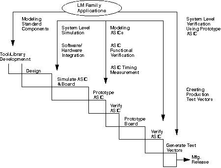
Figure 4.2-4. LM Family usage in the design cycle.
The LM Family modelers can be used to perform software/hardware integration by executing software on a simulated design before investing in prototype hardware. Sections of code can be compiled and stored in simulated memory. This storage allows the use of diagnostics, test, or application software as input to the simulation to verify the hardware design. The accuracy of the Logic Model ensures that if the tests complete successfully, the hardware will work.
The accuracy of Logic Models improves the overall accuracy of the simulation, and it improves the performance of the modeler during simulation. Since the modeler is controlled by the simulator, the designer needs to learn only the simulator's user interface. System-level simulation using the LM Family modelers is of particular benefit when designing ASICs. Before ASIC fabrication, system-level simulation (using Logic Models for standard components and for existing ASICs) verifies ASIC performance in the system. While chip-level simulation (the simulation of the device on its own) verifies the internal functions of the ASIC, only system-level simulation can verify the functionality of an entire system, including multiple devices or even multiple boards.
Using the modeler, a designer can functionally verify prototypes without any specialized knowledge of tester formats, using the familiar simulator interface or the "Play Vectors" utility to apply test inputs and compare results. In addition, the LM Family's timing measurement capability allows the designer to measure the actual delays on device pins identified as outputs and I/Os, to an accuracy of +/- 2 ns or +/- 2% of the measured delay.
The LM hardware modeler supports System-level verification with a prototype ASIC. Once a Logic Model of the ASIC has been created, it can then be used in performing a complete system simulation prior to creating the system prototype. The Logic Model in the simulation verifies the behavior of the ASIC in the system, speeds the simulation (since the hardware model is used in place of a gate-level representation), and helps to create additional ASIC test vectors. Worst- case simulation with minimum/maximum delay values can be performed using the Logic Model of the prototype; final silicon is not required, because delays may be read from a user-provided timing file.
The modeler hardware consists of the following elements:
LM Family Software - The LM Family modelers software is composed of the Runtime Modeler Software and the Host Computer Software. The LM Family's Runtime Modeler Software is the software that controls modeler operations and provides the main modeler functionality. The Runtime Modeler Software is downloaded from the host system and executes on the modeler. It includes the network support software for the modeler as well as the modeler control software. The Host Computer Software executes on the host system and includes the following:
Logic Models are complete and ready-to-use hardware models for use with the LM Family modelers. Each Logic Model consists of the following:
This library contains SSI, MSI and memory components, including a VHDL Test Bench with each model.
NeoCAD's FPGA Foundry is a device-independent toolset for the implementation of Field Programmable Gate Arrays (FPGAs). Design entry can be via an HDL program or the Mentor Graphics Design Architect schematic capture package with one of the supported libraries (NeoCAD, Xilinx, Actel, or any Viewlogic library). NeoCAD will accept a number of industry-standard netlist formats. FPGA Foundry translates the design into the NeoCAD device-independent database, maps the logic into a target architecture. FPGA Foundry PAR implements the design using an advanced, timing-driven place and route tool. With the timing-driven capability the user is able to specify timing preferences (clock frequency, net delay, path delay, skew) which are used during the place and route process to give the user the desired solution with fewer iterations. NeoCAD EPIC (Editor for Programmable ICs) is an advanced device-independent graphical editor which allows the user to view and alter the implemented design. FPGA Evaluator lets the user assess the viability of many different FPGA device alternatives in a single, consistent design environment. Assisted Device Selection performs a physical mapping of the design to each selected architecture. This determines whether the design will physically fit into the selected devices. Assisted Speed Grade Selection performs a static timing analysis of the design in each family and speed grade to determine which speed grades are most appropriate for the design. The analysis is performed based on the user's timing constraints. Finally, the timing-driven place and route can be performed on each candidate device.
The TDS software system is designed to provide all the tools needed to manage the behavioral data associated with an electronic product development cycle. With TDS, data is generated, reformatted, stored, analyzed, modified, and transformed into test programs to support all phases of design and production.
Data can be used from many sources. Data from most simulators can be processed and existing test programs can be used as a data source. Data can be viewed with the TDS tools and then quickly analyzed for completeness and adherence to specifications. In addition, the capability to check data compatibility with the intended tester.
Modifications of the waveforms including adding or adjusting timing information, aligning signal edges, eliminating unnecessary pulses, and eliminating hazardous test conditions can be accomplished. Output can be generated for resimulation or for production of high quality test programs for the tester of choice.
The TDS software system consists of many modules. The components of the TDS software system are:
Visual HDL provides a complete design environment for system designer, ASIC designers, FPGA designer, and simulation model developers. Designs are entered graphically and verified though simulation and debugging. Designs may be entered using block diagrams, state diagrams, flowcharts, and truth tables. The output is synthesizable VHDL code.
The SimMatrix co-simulation products from Precedence allow the designer to perform system level simulations in a heterogeneous design verification environment such as the one required for the Architecture Verification and Detailed Design portions of the RASSP design cycle. System level simulations frequently need models represented at different levels of the design abstraction hierarchy. The SimMatrix technology allows simulations combining gate-level, accelerated gates, emulated gates and VHDL all in a common design environment.
Designs utilizing two or more simulators, such as the QuickVHDL simulator from Mentor and the Quickturn emulator, are hierarchically partitioned within the original design environment. During co-simulation, the backplane transparently manages the flow of information and orchestrates synchronization between the simulation algorithms, ensuring high performance as well as flexibility. The graphical and textual user interface and debugging environment of each simulator is preserved and available to the designer.
The I-DEAS Master Series suite of mechanical CAE/CAD/CAM tools includes (but is not limited to) the following:
The Master Modeler is a high performance 3D design system and the multi-purpose geometric modeling foundation of I-DEAS. The solids-based approach aids design productivity by easing construction of complex geometry, facilitating design changes, automatically removing hidden lines, directly calculating mass properties, and providing an accurate part definition for NC (numerical control) machining. The SDRC data management system maintains associativity between the master model, drawings, finite element models, and NC (numerically controlled) data.
Utilizing the variational solid modeling capabilities of Master Modeler, Sheet Metal Design software automatically incorporates user-definable bend tables, stress reliefs, and shrinkage allowance into solid models to facilitate rapid design and evaluation of sheet metal parts. A catalog of sheet metal features including punches, tabs, and other features allows the designer to add final detail to the part to capture true design intent. The solid sheet metal model can be unfolded and used to create fully associative flat pattern production drawings, and numerical control tool paths for manufacturing.
I-DEAS Drafting is used to create detailed production mechanical drawings. It can be implemented as a tool for documenting solid models created in Master Modeling or as a standalone 2-D drafting system. It is seamlessly integrated with the other I-DEAS modules and utilizes the Dynamic Navigator style of user interaction. Orthographic, section, detail, and auxiliary views are easily created from the master model.
I-DEAS Tolerance Analysis software provides the capability to evaluate the tolerance specifications of a design to reduce the chance of assembly interference problems. It uses variational geometry techniques to determine worst case and statistical tolerance stack up between mating parts in a complex assembly. A user can measure the sensitivity of a critical dimension in an assembly to changes in individual constraints. Tolerance models are created by relating fully constrained 2D variational sections or wireframes.
I-DEAS Mechanism Design software is an integrated capability for simulating complex motion of articulated mechanisms. Using assemblies created using Master Assembly, joint constraints and connectivity information are created, and motion and loading inputs are applied. I-DEAS then calculates resultant forces, motions, and velocities.
View and markup is used by checkers to check the final drawings from I-DEAS Drafting, or by design review teams to evaluate designs from I-DEAS Master Modeler. An integrated Geometric Dimensioning and Tolerancing syntax checker simplifies the drawing checking task. It provides for drawings to be marked with notes, new geometry added, wrong geometry crossed-out, and dimensions highlighted.
I-DEAS Finite Element Modeling (FEM) software provides comprehensive capabilities for building finite element models and reviewing analysis results. It uses the Master Modeler geometry directly, and includes the fundamental modeling functions of automatic mesh generation, application of loads and boundary conditions, and model checking. Post-processing functions allow the recovery of analysis results and provide extensive graphical and numerical tools for gaining an understanding of results. A rules-based Simulation Advisor is available to guide the user through the analysis process.
The Optimization software assists the user in the use of analysis results to directly drive design improvements. Structural optimization can help weed-out poor design concepts as well as identify and improve promising ones. It can also be used for fine-tuning designs by minimizing weight or cost, while insuring they will meet all structural performance requirements. Optimization uses the finite element analysis approach to simulate structural performance.
I-DEAS System Dynamics Analysis software provides an interactive, graphics oriented capability for simulating the dynamic performance of mechanical systems. The user can model a mechanical system, analyze its modal parameters, and evaluate its response to applied forces and enforced motions. System models may be assembled from components defined from FEA analysis, solid modeling, as well as experimental modal analysis.
Quickturn's System Realizer Family of Modular Emulation Systems and the Logic Animator rapid prototyping system are used to generate a reprogrammable physical prototype, or "virtual silicon" representation, of their electronic circuit designs. This representation is then available for concurrent verification of the entire target system, including system software and applications, and iterative design changes, all prior to silicon fabrication.
VHDLCover provides code coverage analysis for VHDL code. Simulation verifies that the portion of code being tested works correctly. VHDLCover analyzes the code and indicates how thoroughly the design has been tested and what portions have not been tested. It provides insurance that every line of VHDL code has been tested and redundant code is eliminated.
Teradyne's VICTORY software fully automates test generation for boundary-scan devices in boards or modules using full or partial scan technology. For individual boundary-scan parts, VICTORY automatically generates in-circuit test patterns. For boards or modules with full networks of boundary-scan parts, VICTORY generates interconnect test patterns that provide 100% pin-level fault coverage. VICTORY also supplies tools for testing the internal logic of boundary-scan devices and for testing conventional devices or device clusters, using the scan cells connected to their inputs and outputs as virtual channels.
VICTORY generates four kinds of scan tests: boundary in-circuit tests, virtual interconnect tests, virtual component/cluster tests, and boundary functional tests. VICTORY diagnostic software helps resolve boundary-scan faults during test. VICTORY also provides Access Analyzer software to help engineers optimize boards for testability, cost, and performance before layout begins.
The boundary in-circuit tests provide automatic generation of boundary in-circuit test (BICT) patterns using information from a BSDL (Boundary Scan Description Language) model, correct analysis of device constraints like pins tied to power or ground, pins tied together, or pins without physical access, automatic detection of stuck-at pins and interconnect opens without manual probing, and automatic disabling of the boundary-scan chain during in-circuit testing.
Virtual Interconnect tests (VIT) provide automatic generation of test patterns for 100% pin-level fault coverage, automatic detection and diagnosis of stuck-at pin faults and shorts and opens between boundary-scan parts without manual probing, automatic detection of shorts between boundary-scan nets and conventional logic nets that have bed-of-nails access, and automatic conversion of parallel patterns into serial, tester-compatible format with comments for simplified debugging.
Virtual component/cluster tests (VCCT) provide virtual bed-of-nails controllability and observability for testing non-scan circuitry without physical access, automatic serialization of parallel test patterns for testing individual non-scan devices or clusters of non-scan devices via the boundary-scan path, automatic organization of bit-level data for synchronous application via a combination of real and virtual channels, and simplified circuit initialization by direct forcing of inputs to desired states.
Boundary functional tests (BFT) provide thorough testing of the test access port (TAP) and 1149.1 registers, automatic testing of core device logic through the TAP using the new Serial Vector Format (SVF) interchange standard, compatibility with test techniques such as INTEST, BIST, and internal scan, made available by the device designer, and dynamic testing of device performance by applying built-in-self-test (BIST) instructions via the scan chain where the system clock is used.
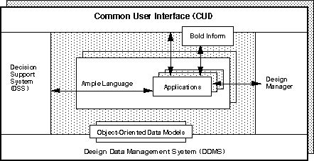
The FALCON Framework is a common environment in which all Mentor Graphics and OpenDoor applications run. These applications use the FALCON Framework to provide a common user interface, text editor, and decision support system. See Figure 4.3-1 for a diagram of the FALCON components. The FALCON Framework consists of the following.
Figure 4.3-1. FALCON Framework components.
The user interface that is used in all Mentor Graphics applications; it supports Open Software Foundation (OSF)/Motif standards to maintain a similar look and feel to all aspects of the user interface.
Design Manager is an application that allows you to view and navigate your design data; move, copy, and manage your data; and invoke applications. The Design Manager manages design objects. Design objects are related sets of files and directories that describe different aspects of
the design. Each design object includes a set of object attributes, including identity, type, version, and properties.
BOLD Browser is an application that displays on-line documentation and help information.
Notepad provides a text editor that operates in a window of any application. Notepad is a text editor that includes easy-to-select font sizes and styles, search-and-replace capabilities, auto-wrap, auto-deletion, and file manipulation. Notepad is programmable and has a large set of user-callable functions.
DSS is an application, and a tool on which you can build your own applications, that can be used to access and analyze design data, and to manage design processes. The DSS architecture has three main features:
AMPLE is a powerful extension language that supports customization and integration throughout the FALCON Framework and all FALCON-based applications. The FALCON Framework is an open framework. This means that you can add your own applications and data to the framework and have them share many of the features of the FALCON Framework environment. Many third-party developers also have versions of their applications designed to run in the FALCON Framework. AMPLE supports structured, procedural programming with a rich set of data types, operators, control structures, and procedural interfaces. Using AMPLE, the Common User Interface can be customized and extended. Support for concurrent engineering and rapid application prototyping are available through AMPLE and DSS. Design applications integrated within the FALCON Framework can also be customized and extended with AMPLE. New commands and functions can be written in AMPLE. Routine operations can be automated by recording user actions as replayable AMPLE transcripts. AMPLE supports dynamic linking with libraries and functions written in the C programming language. Existing in-house and third-party solutions can be integrated into the FALCON Framework and access to these solutions can be provided from within AMPLE.
RASSP CDRL A007 - 6/98 4-3
cad system description Baseline 2.0
Next: 5. Design for Test Tools
Up: Appnotes Index
Previous:3. Hardware/Software Co-Design Tools
4.3.1 Framework (Mentor's FALCON)
4.3.1.1 Common User Interface
4.3.1.2 Design Manager
4.3.1.3 BOLD Browser
4.3.1.4 Notepad
4.3.1.5 Decision Support System (DSS)
4.3.1.6 AMPLE
![]()
![]()
![]()