![]()
![]()
![]()
Next:4.0 Hardware Design Tools Up: Appnotes Index Previous:2.0 System Design Tools
Much of the work normally associated with applications, control, and communications software development is performed in the Architecture process in the RASSP methodology. The software side of hardware/software co-design is concerned with aggregating and/or translating the compiled HOL code verified at the architectural level to downloadable target code.
Downloadable code is generated by taking autocoded and hand-generated portions of application and control code, and combining them with the communications and support software into a single executable for each processor. The run-time system, which provides the reusable control and graph management code, will have all the hooks required to interface with the support code. Figure 3.1-1 shows the software architecture.
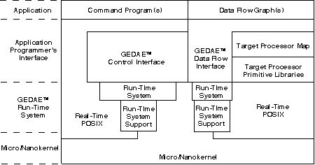
Figure 3.1-1. Software architecture.
The signal processing software development is data flow graph (DFG) driven.
The Architecture definition process transforms requirements into candidate architectures of software and hardware elements through hardware/software co-design and co-verification at all steps. It is composed of three major steps: Functional Design, Architecture Selection and Architecture Verification. The Functional Design step provides a more detailed analysis of the processing requirements resulting in initial sizing estimates, detailed data and control flow graphs for all required processing modes to drive the hardware/software co-design, and the criteria for architecture selection. During Architecture Selection, a trade-off analysis based on the established selection criteria results in the specification of the detailed architecture, software partitioning and mapping. Figure 3.1-2 depicts the major Hardware/Software Co-design tools. The virtual prototype, VP1, produced during Architecture Selection is not a full system prototype, since function and performance are simulated independently and may or may not be coupled with the overall control mechanism. During Architecture Verification, virtual prototype VP2 is produced representing a functional and performance description of the overall design. This prototype may have models at varying levels of abstraction, requiring multi-domain simulation capabilities.
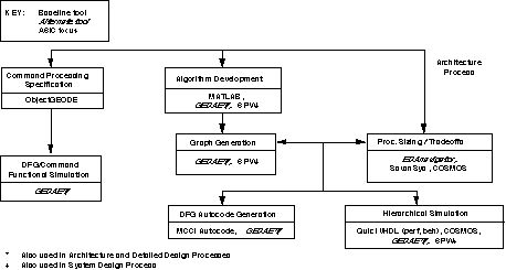
Figure 3.1-2. Architecture selection toolset.
The architecture model, taken as a whole, consists of the structure interconnection of the components, their abstract VHDL models, and the associated software descriptions. The VHDL models of programmable units are designed to interpret the data files produced by the software design process to facilitate hardware/software co-simulation and co-design. The architecture model forms the executable specification of the architecture design, and the VHDL component models form the executable specifications of the hardware components that are passed on to the hardware design process. Associated with each VHDL component model is a VHDL test bench. We design the VHDL test bench for each hardware component before the component model is designed. Since the architecture model is more detailed than the system-level performance model, the more precise results of its execution are back annotated to the system model. Likewise, as we obtain the results from the more detailed hardware models in the hardware design process, they are back-annotated to the architecture and system models.
The results of the System Design process are architecture-independent processor requirements. The Architecture Design process proceeds as follows:
For each candidate architecture develop:
The RASSP Architecture design toolset for Hardware/Software Co-Design includes:
NetSyn is used to perform application specific network definition and synthesis and analysis. The primary objective is to provide a smart designer with the tools that will enable him to mostly automatically synthesize and analyze a network. The system provides facilities for synthesizing and evaluating numerous alternatives. It enables the automated synthesis of network solutions based totally on the requirements and constraints imposed by the designer. By deriving solutions from requirements and constraints, the system ensures that solutions meet specifications and enables the quantification of the impact of specification changes.
The NetSyn synthesizes a heterogeneous multiprocessor network consisting of processors, memories, input/output, and communication entities to execute an application represented in graph form. NetSyn co-designs the hardware and software at a very early stage of the design. It automatically generates proof-of-concept and pre-production prototype designs and automatically assigns the software elements to processors in the network. NetSyn enables the user to rapidly evaluate alternative network designs by trading off hardware against software to synthesize the most efficient network architecture that meets the requirements.
SavanSys is a tradeoff analysis tool focused on packaging and interconnection of high-performance electronic systems. Given physical descriptions of the components to be interconnected and packaging technology selections, it will produce performance metrics including system size, routing, thermal, electrical, reliability and cost analysis for multichip and multiple board systems. Technologies treated by SavanSys include: traditional and fine-line printed circuit boards, low temperature co-fired ceramic and thin-film. Component assembly approaches include wirebonding, TAB, flip chip and single chip packages. Materials are also available for bare die attach, encapsulation, heat exchanger attach, and for defining the bonding and interconnect technologies.
The tool begins by capturing design and performance budgets and constraints. Next, the components (active and passive) to be packaged are described. Component descriptions include the entry of physical (dimensions), material, I/O (number of signal, power, ground, unused), electrical (bias level, logic swing), thermal and manufacturing (cost, tested yield, etc.). All of this information is included in the "chip" class. In addition to these properties, the characteristics of heat spreader and thermal vias are captured as properties of each component rather than the module or board so that they can be easily manipulated on a per component basis.
After the components are described to the tool, they are placed into "partitions." Partitions consist of any subset of the defined components grouped into a few chip package, MCM or printed circuit board. It is through the creation of partitions that complex systems can be built using the tool.
Designers use the Partition Manager to create new parts or import existing parts from external component libraries, distribute components and modules throughout the hierarchy, define substrate and interconnect technologies, and run concurrent analysis on various levels of the hierarchy. SavanSys allows engineers to change design concepts between different components and connectors, packaged or unpackaged ICs, or interconnect and assembly technologies.
The Placement Editor enables engineers to quickly explore the impact of component placement (single or double-sided) on cost, weight, size, thermal, and critical net electrical performances. SavanSys can import and export system packaging specifications, including placements, and component and technology descriptions in formats compatible with PCB and multichip module (MCM) layout tools from Mentor Graphics.
Ptolemy is an environment for simulation and prototyping of heterogeneous systems. It uses modern object-oriented software technology to model each subsystem in a natural and efficient manner, and to integrate these subsystems into a whole. The objectives of Ptolemy encompass practically all aspects of designing signal processing and communications systems ranging from algorithms and communication strategies, through simulation, hardware and software design, parallel computing, and generating real-time prototypes. To accommodate this breadth, Ptolemy must support a plethora of widely differing design styles. The core of Ptolemy is a set of object-oriented class definitions that makes few assumptions about the system to be modeled; rather, standard interfaces are provided for generic objects and more specialized, application-specific objects are derived from these.
A basic abstraction in Ptolemy is the Domain, which realizes a computational model appropriate for a particular type of subsystem. Current examples of domains include synchronous and dynamic dataflow, discrete-event, and domains appropriate for control software and embedded microcontrollers. Domains can be mixed as appropriate to realize an overall system simulation. Some current applications of Ptolemy include networking and transport, call-processing and signaling software, embedded microcontrollers, and signal processing, including implementation in real-time on programmable DSPs, scheduling of parallel DSPs, board-level hardware timing simulation, and combinations of these.
The Graphical Entry Distributed Application Environment (GEDAE™) is a graphical programming tool that facilitates the development of parallel distributed data flow applications on a heterogeneous network of processors. GEDAE™ provides a simple Motif interface, allowing the user to create, edit, control and monitor hierarchical data flow graphs. GEDAE™ 's simple programmer interface makes it possible to easily create primitive function boxes by encapsulating existing software in a C language shell. GEDAE™ maintains much of the efficiency of special purpose code while hiding the details of network interconnection and data flow. GEDAE™ 's data flow control software takes advantage of any data parallelism or pipelining inherent in the constructed data flow graph. Data flow is efficient because objects cast or transfer themselves differently, depending on the type of data transfer, to optimize communications efficiency. An autocode generation capability provides the ability to automatically generate source code for multiprocessors and to efficiently support fine-grained data flow graphs. Currently, GEDAE™ is being enhanced to allow applications developed in a workstation environment to be mapped to embedded processors for efficient execution.
The GEDAE™ software structure, as discussed above, allows an application programmer to develop modules independently of how they are connected. It allows a user to connect modules independently of how they are implemented and where they are executed. Data transfers across the network, data casting (translation) between different data types, and data transfers between host and remote processors are all transparent to the user. Function-box application programmers can develop a module without knowing how it will be used in the system because they do not need to specify how data is transferred. This knowledge is embedded in the input and output data objects themselves. Many standard data types are provided by GEDAE™ and tools for creating new data types are available. The object-oriented nature of the environment cleanly separates function box design, data type design, and user interface design.
GEDAE™ runs on Sun Solaris, HP, NT, and SGI workstations. GEDAE™ is built using readily available network and graphic standards. The only requirements for porting GEDAE™ to a platform is that the TCP/IP protocol and the X windows graphics standard be supported. GEDAE™ uses the Sun standard XDR protocol to provide data translation between various machine types.
An Application Interface Builder (AIB) has been developed by ATL under the RASSP program to generate the application specific Command Program Interface (CPI) instantiation that fills the gap between the CPI and the Data Flow Interface (DFI). Figure 3.2-1 illustrates this gap.
The control software developer issues a mode change request via the CPI and the interface software constructed by the AIB will provide the detailed sequence of commands via the DFI to implement the request. The CPI instantiation consists of calls to the DFI based on the specific set of modes/submodes for the application, the set of graphics developed to perform the application, and the correlation between the two sets. The capability of the AIB will be commercialized as part of the GEDAE™ product.
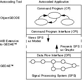
Figure 3.2-1. Application Interface Builder bridges gap between data flow and control flow.
PRICE is used in conjunction with SavanSys to provide cost estimates for the candidate architectural configurations. The characteristic information derived from SavanSys is used by Price to develop data for the cost/performance trade-off matrix.
PMW, Performance Modeling Workbench, is a GUI front-end and set of postprocessing tools for the HTC (Honeywell Technology Center) PML (Performance Model Library). The PML is a set of abstract VHDL models representing the various network architecture components that comprise a multi-processor DSP system. Such components include generic processor nodes, buses, and network switches. PML resolves the components at the so-called "performance modeling" level, where time related issues such as latency, throughput, and resource utilization are concerned. Application data values are not evaluated by the PML models.
PMW provides a convenient graphical way to configure the purely textual PML models of a hardware system. PMW also provides a graphical method to capture application software in a data-flow-graph that in turn drives the hardware models during simulation. PMW provides a mechanism for building and launching the VHDL simulation and collecting the results. The simulation results are analyzed through PMW's time-line displayer utility.
The Reliability, Availability, Maintainability and Integrated Logistics Support (RAM-ILS) tools are integrated in a UNIX graphics user interface. A second interface has been generated that is embedded in the RASSP design framework. Both graphic user interfaces use connectivity drawings to represent simulation models. The RASSP RAM-ILS toolset consists of tools for pre-design architecture simulation, during design verification and assessment, and component selection for final detailed design. There are tools for success analysis, decision analysis, fault tree analysis, failure modes and effects analysis, availability analysis, reliability analysis, maintainability, and life cycle support costs.
RTM provides a requirements engineering toolset designed to ensure that all project work is performed against a customer stated requirement and that requirements traceability, compliancy and quality auditability are maintained throughout a project lifecycle. The RTM project database holds information pertaining to all phases of the project, but focuses primarily upon the system requirements and the tracking of these requirements through the product lifecycle. During the architecture definition process, hardware/software co-design tradeoffs are conducted to determine the architectural entities of the signal processor. The requirements for each of these architectural entities are established during this process and these requirements are traced to the signal processor requirements through the use of RTM.
SPW will be used to explore algorithms and function partitioning issues including assessing the complexity of the required processing. The SPW tool (or the JRS graphing tools with NetSyn) will provide the dataflow graph which drives the multiprocessor design.
The MATLAB functions developed in the System design effort will be used to verify the correctness of the architectural implementation.
The mixed domain simulation backplane is used when high-risk design elements spawn prototyping activities resulting in more detailed designs running on any one of a number of lower level simulators. The detailed design can then be co-simulated with the higher level architecture simulations for verification.
The QuickVHDL family of products consists of a VHDL compiler, an interactive simulator, and a VHDL source language debugger. Multiple interactive windows allow a designer to simultaneously view the design hierarchy and VHDL source code, display variable and signal values, control the simulator, schedule processes, and display simulation results in both list and waveform outputs. The simulator, developed by Model Technology, combines the best features of previous interpreted and C-compile methods, resulting in faster throughput (as a function of compile and simulation times). Benchmarks show that the QuickVHDL "direct compile" technology, in which VHDL code is directly compiled to the instructions of the host RISC simulation engine, is between 2-10x faster than other methods.
The current level of integration of QuickVHDL allows a designer to enter VHDL code, compile, and debug compile errors within Design Architect. Graphically-entered structures in Design Architect may also be passed to QuickVHDL and schematic cross probing is supported.
The Autocoding Toolset is designed for the development of large, complex parallel signal processing applications that require significant processing power. The toolset contains a set of integrated tools that translate an application specified as a set of PGM graphs into a set of 'C' source code files which are target specific. Applications are specified as data flow graphs using a formal graphical language (PGM) and a target independent library of signal processing routines. The graphs are partitioned into independent execution units which are then assigned to specific processors. Through partitioning, the user can eliminate many execution bottlenecks such as data transfer contention. Processor specific support for target independent signal processing routines is incorporated in the Autocoding Toolset as optimized, target specific implementations of these routines utilizing high performance math libraries from board vendor or third parties.
ObjectGEODE from VERILOG enables the generation, verification and validation of target code for the command program
ObjectGEODE can be used to generate a graphical representation of the command program, verify and validate it in a standalone simulation and then automatically generate target code.
The design flow using ObjectGEODE begins with requirements analysis and development of an extended finite state machine model of the system. This model includes objects of the system as well as a representation of external actors. Use-Scenarios are described by means of MSCs (Message Passing Charts). The architecture of the system is then designed using the SDL (Specification and Description Language) concepts of system, block and processes to create an SDL Hierarchical Diagram and a set of SDL Interconnection Diagrams. Test design is performed in parallel with the architecture and detailed design using the Use-Scenarios. The detailed design step consists of specifying states and state transitions at the process and procedure level.
The developer rapidly prototypes the application and verifies and validates it using the ObjectGEODE simulator. The code translated from the logical architecture of the system as represented by SDL is partitioned to run either on the system hardware. Actual "C" code is generated which is supported by numerous RTOS including Microtec Research Inc., VRTX, Wind River Inc. VXWORKS, etc. In addition, the 'C' code can also be tailored run using a different RTOS. The tool supports software reuse by easy incorporation of heritage software libraries into both the graphic model and generated source code.
BEACON converts user specified block diagrams into a variety of software languages, including FORTRAN, Ada and C. It also generates documentation and test vectors for unit tests. The generated software includes on-board diagnostics, performance monitoring, I/O services, startup and shutdown procedures.
Harris EDAnavigator is an alternative tool to Savantage's SavanSys. With Harris EDAnavigator, the designer can explore various system-level hierarchical partitioning, packaging design, placement, and interconnect choices with respect to user-selected physical metrics such as electrical and thermal performance and routability without waiting until after layout.
The Harris EDA tool has an advanced partitioning/packing algorithm and will automatically define hardware partitions based on grouping components with maximum interconnect. Harris EDAnavigator does parametric placement based on simulated evolution, minimizing total interconnect, adhering to net-timing and providing congestion avoidance.
SPEAR will provide a generalized but customizable multiprocessor debugging environment. The tool provides a common user interface to multiple target-dependable debuggers and supports the simultaneous interactions with distributed processing elements for monitoring, controlling, sampling, and instrumenting the multiple processes executing in the target system for the purposes of detecting and localizing errors. SPEAR does not replace the many excellent debuggers targeted to specific commercially available processors and boards, but rather provides a framework within which uniprocessor debuggers may be integrated to support multiprocessing.
In RASSP there is a need for trace information document the behavior of the system's components. This information is useful for debugging, verification, and testing of both the correctness of the software, as well as its performance characteristics.
The PIE/RASSP system is designed to address the trace generation and visualization needs of the RASSP community. The project consists of two major tools, the PIE/RASSP Event Browser and the PIE/RASSP Development System, that are directed at making the testing and verification process as easy and painless as possible.
The first tool is the PIE Event Browser. This tool is intended to provide much needed visualization capabilities to existing trace generation tools. Many systems rely on developers examining ASCII trace output files or writing custom tools for specific trace formats. The PIE Event Browser provides the developer with a way to quickly visualize any trace output.
The second toolset being developed as part of the PIE/RASSP project is the PIE/RASSP Development System. This toolset represents many man years of development that has been focused on providing the RASSP effort with a DSP application instrumentation, testing and evaluation capability.
RASSP CDRL A007 - 6/98 3-3 cad system description Baseline 2.0
![]()
![]()
![]()
Next: 4.0 Hardware Design Tools Up: Appnotes Index Previous:2.0 System Design Tools
Approved for Public Release; Distribution Unlimited Dennis Basara