Next: 6 System Design Process Detailed Description Up: Appnotes Index Previous:4 Unifying Processes and Roles in RASSP
![]()
![]()
![]()
![]()
Next: 6 System Design Process Detailed Description
Up: Appnotes Index
Previous:4 Unifying Processes and Roles in RASSP
Exploring the RASSP design process may be performed in multiple ways in this Section as follows:
Table 5 - 1 list all of the process steps for RASSP and provides direct links not only to the detailed IDEF3X chart but also to the workflow implementation of that process with the Intergraph Design Methodology Manager. As in the second option above, links to the textual description are also provided.
The RASSP Model Year Architecture(s) must be supported by the necessary library models to facilitate trade-offs and optimizations for specific applications. Reusable hardware and software libraries facilitate growth and enhancement in direct support of the RASSP Model Year concept. The notion of Model Year upgrades is embodied in the reuse libraries and the methodology for their use. As technology advances, new architectural elements may be included in the library. Rapid insertion of a new element into an existing, RASSP-generated design is the goal of the Model Year concept. Details of the Model Year Architecture concept are more fully discussed in the Model Year Architecture application note.
The first major cycle of the spiral shown in Figure 4 - 1 results in a requirements specification that was captured in an appropriate tool; it is the first instantiation of a virtual prototype (VP0). This information is then translated into simulatable functions, which we refer to on RASSP as an executable specification. This cycle represents the first level at which requirements are specified so that we can readily match with simulators to verify performance and functionality in an automated manner. In this phase, processing time is allocated to functions and functional behavior is defined in the form of executable algorithms. At this point, all signal processing functions are implementation-independent. High-risk items can spawn prototype analysis and development efforts in a mini-spiral. The executable specification represents a major portion of the systems design information model. This process results in a System Definition Review (SDR) based upon VP0.
A major portion of the systems behavioral definition is in terms of algorithmic functionality. Generating an executable version of the algorithms using systems-level tools is part of the systems effort. In addition, the detailed specification of all messages that must be passed to and from the signal processor must be generated, along with the definition of all required mode transitions.
Click on Section 6.0 to go to a more detailed description of the System Process.
Click on System Process Application Note to go to the application note that not only discusses the methodology but also the use of the Integrated System Engineering tool environment.
Click on System Design to go to the IDEF3X chart for this effort.
The architecture design process is a new hardware/software codesign processin the RASSP methodology for high-level virtual prototyping and simulation. Traditionally, the architecture definition has been performed partially in the systems design and partially in the hardware design. RASSP has redefined the major processes by product maturity versus functional area into systems, architecture, and detailed design. Hardware/Software codesign encompasses architecture and detailed design. The primary concern in the architecture design process is to select and verify an architecture for the signal processor that satisfies the requirements passed down from the systems definition process. Although the architecture must include everything required in the signal processor, including any control processors which may be required, this discussion focuses on the approach to defining the number and connectivity of the signal processors required to meet the processing requirements. The overall task is to:
Concurrently, each selected architecture is evaluated for size, weight, power, cost, schedule, testability, reliability, etc. so that a more informed assessment can be made. Software and architecture performance is simulated concurrently so that software performance has a direct impact on the selection of an architecture. This direct coupling through co-simulation immediately inhibits any inclination to design the hardware and make the software fit later.
The architecture design process is library based and Data Flow Graph (DFG) driven. Reuse of both architecture elements and software primitives significantly shortens the design cycle. Candidate architectures are constructed from library models. The signal processing software is then partitioned and mapped to the each candidate architecture. A VHDL simulation for the architecture is also constructed and then simulated to estimate performance. Processor behavioral and performance simulations support trade-offs. Mixed levels of simulation (algorithm, abstract behavioral, performance, ISA, RTL, etc.) are used to verify interaction of the hardware and software. These models are largely hierarchical VHDL models of the architecture. We choose the models, to the maximum extent possible, from the Model Year Architecture elements in the reuse library. The design team develops and inserts new required library elements into the reuse library to support this design phase. The executable specification has now evolved into a more detailed set of functional and performance models that are architecture-specific. Software algorithm implementations are also now specific to the candidate architecture(s). We conduct an Architecture Design Review based on VP1 and VP2 when the architectural trades are completed and the design has been verified to a high degree of confidence. This process is iterated at the high level to achieve one or more satisfactory designs.
The process is supported by an integrated set of tools to foster iterative design and risk reduction. This results in a more detailed evaluation of architectures (from all perspectives ) at the early stages of design, which eliminates the false starts that are costly later in the design cycle.
At the conclusion of the systems/subsystems process, a processing requirements specification (both functional and performance) that describes the signal processing functionality is provided. Included in these requirements is a description of all the required interfaces between the signal processor and the outside world, such as mode transition requests, signal processing parameter observation and/or parameter setting, and I/O initiation or termination requests. All requirements flowed down from the systems processare traceable throughout the architecture definition process. Candidate architectures are evaluated against these requirements during the hardware/software codesign process. Updated values of the requirements metrics for candidate architectures are passed back to the systems process. In the event that the requirements cannot be met, additional trades are conducted at the systems level. Note that these inputs to the architecture definition process are completely independent of architecture/processor implementation. It is the objective of the architecture process to transform these processing requirements into candidate architectures and to select and verify an implementation approach.
The architecture design process transforms processing requirements into a candidate architecture of hardware and software elements, through hardware/software codesign and co-verification at all steps. As such, the architecture design process incorporates both hardware and software aspects. This results in a detailed behavioral description of the processor hardware and the appropriate software required to verify these descriptions. In addition, this portion of the process also develops and verifies the implementation-specific portions of both the application (algorithm) and control/support software.
The software portion of the architecture process deviates significantly from traditional (functional decomposition 2167A) approaches. The partitioned software functionality can be broken into four major areas:
The intent of RASSP is to automate the first three to the maximum extent possible. This will be accomplished using a graph-based programming approach(es) that supports correct-by-construction software development based on algorithm and architecture-specific support library elements. The execution control of these graphs is provided by a run-time system that provides reusable data flow control, which extends the notion of reuse beyond signal processing primitives.
The general command/control software development (see Autocoding for DSP Control application note) will use emerging, object-oriented code development, documentation, and verification tools. The command program interfaces with the outside world via a messaging system and translates messages into graph and I/O control commands for execution by the run-time system. We design all the non-data flow graph software required for the signal processor during the architecture process. We functionally simulate the joint operation of graph-based and non-graph based software to validate the proper interaction of the command program with the data flow graph execution.
As part of the RASSP methodology, as much design, costing, testing, and manufacturing information as possible will be used throughout the architecture design process through concurrent engineering that is supported by tool integrations and design advisors which cover a wide range of disciplines. The architecture process supports a more formalized trade-off process in which all these disciplines provide valuable inputs.
Click on Section 7.0 to go to a more detailed description of the Architecture Design Process.
Click on Hardware/Software Codesign Application Note to go to the application note that describes the latest developments in this process as well as the use of the integrated architecture toolset. This will also provide links to more detailed application notes that describe the use of the various technologies involved with this process. These links are also listed below and will be found throughout the detailed discussion in Section 7.0
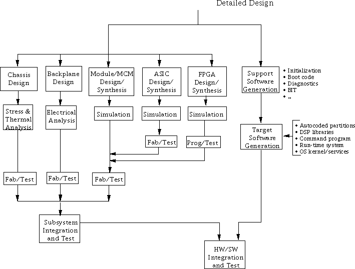
We partition and develop designs at the behavioral-level (RTL or higher) for processor-level nodes to the appropriate level for all necessary components. This includes ASIC, MCM, and board-level designs, as well as backplane/chassis designs. The process incorporates mechanical and manufacturing elements to ensure that designs meet all specifications for the particular applications. From an industry standpoint, the detailed design process is the most mature area of design, and the improvements on RASSP are optimizations to support rapid prototyping. Toward this end, the process heavily favors two areas:
In the case of software, we must generate any support code that is target specific for the signal processor that has not been completed. This includes initialization, bootup, diagnostics, test software, and any support software required for integration and test which is not part of the operational software. All the software is compiled and verified (to the extent possible) on the final virtual prototype before the detailed design review.
Like the architecture process, this portion of the methodology supports hardware/software codesign, as these elements are fully verified together on the virtual prototype up until the design is released to manufacturing. This virtual prototype iteration (VP3) involves the detailed design of software and hardware elements. As with the prior processes, we design and verify both hardware and software via a set of detailed functional and performance simulations. When this process is completed, the design is established, resulting in a fully verified virtual prototype of the system. We revalidate software that was verified during architecture verification as we develop more detailed models for any of the components. This process provides continual verification as the designs progress toward physical hardware. The transition of these designs to manufacturing is supported by the RASSP enterprise system to provide electronic linking capabilities supporting both concurrent interaction between design and manufacturing, and direct transfer of designs to manufacturing sites.
During the hardware portion of the detailed design process, we transform behavioral specifications of the processor into detailed designs (RTL and/or logic-level) through a combination of hardware partitioning, parts selection, and synthesis. Detailed designs are functionally verified using integrated simulators, and performance/timing is also verified to ensure proper performance. The process results in detailed hardware layouts and artwork, net lists, and test vectors that can then be seamlessly transitioned to manufacturing and test via format conversion of the data. We generate the entire design package required for release to manufacturing for the Detailed Design Review based on VP3, which corresponds closely to today's Critical Design Reviews (CDRs).
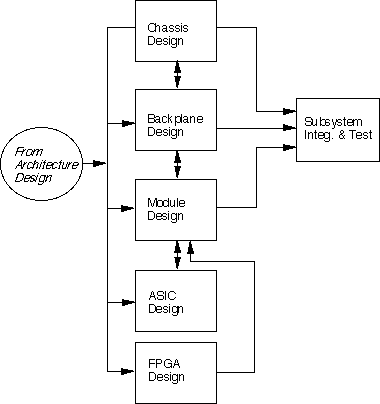
At the top level, the detailed design process for hardware is, for the most part, the same for boards, MCM, ASICs, etc. However, at the lower levels, these designs are quite different and use different tools. The hardware process is partitioned as a function of the hardware element, e.g., chassis, backplane, board, chip, etc.
We start the overall hardware design process with the subsystem (e.g., a signal processor) components definition requirements from the architecture verification process. This is documented at the level of detail of a Type C specification (MIL-STD 490). Architecture verification previously analyzed these requirements, performed architecture trade-off studies (supported by VHDL simulations at the algorithm and architecture level), partitioned the functional requirements into analog/digital/mechanical, and generated documents for all individual elements, including backplanes (frames/cabinets), modules, and ASICs.
The hardware design process flow is shown in Figure 5 - 3. In RASSP, partitioning is driven by component requirements from the architecture process, with a heavy predisposition toward using library-based components to support the in-process design concept. Where possible, we use off-the-shelf modules, MCMs, ASICs, chassis, and backplanes, and we will be aided by knowledge-based advisors with data on available hardware elements to drive synthesis-based approaches. We will specify off-the-shelf hardware for procurement, and we will design custom hardware for fabrication. All hardware must be modeled or must have testbed hardware in place for joint hardware/software simulation and verification. The concept of hardware/software codesign at this level is a new element introduced by RASSP.
In interactive logic design, we develop a structural VHDL description from the algorithm architecture level-VHDL descriptions, which include DFT structures. We simulate this model to verify functionality and performance, then synthesize it, generate a layout, and perform a thermal analysis. Back-annotated simulations are done followed by a critical design review after verification. We then manufacture hardware and test it.
Click on Section 8.0 to go to a more detailed description of the Detailed Design Process.
Click on Detailed Design to go to the IDEF3X chart for this effort.
5.0 RASSP Design Process Description
5.1 Overview
This section addresses the portion of the overall methodology that relates to the RASSP design process. The design process is detailed in Figure 5 - 1. The system design, architecture design, detailed design processes, and library population are addressed in individual subsections. [Click in the shaded boxes of Figure 5 - 1 to obtain the textual overview for that box as well as additional links for more detailed descriptions] Software is discussed in the architecture, detailed design, and library population processes as part of hardware/software codesign; it is also addressed separately to present a consolidated picture. The bold arrow between the individual processes and the library population in Figure 5 - 1 is meant to convey that the overall methodology is an iterative process with feedback from any process to preceding processes. The development of new library elements (software primitives or architectural elements) can be initiated anywhere within the design process, as the need arises.
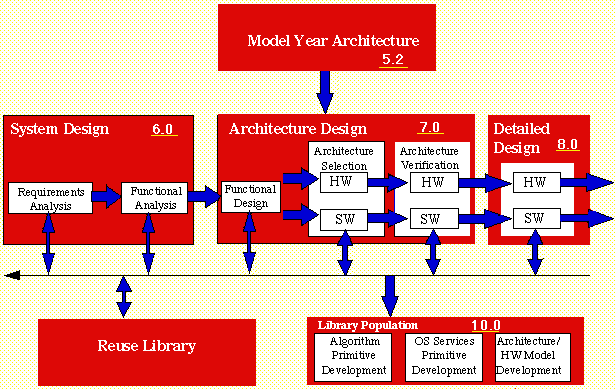
Design Phase IDEF3X Model DMM Workflow System Design X Requirements Analysis
X X Functional Analysis
X X System Partitioning
X X Architecture Design X Functional Design
X X Architecture Selection
X X Architecture Verification
X X Detailed Design X X X X X X X X X X X X X X X X X X X X X X X X X X X X X X X X X X X X 5.2 Model Year Architecture Overview
To dramatically improve the process by which complex digital systems are specified, designed, documented, manufactured, and supported requires a signal processing design methodology that recognizes a number of application domains. Within these domains are many common characteristics that can be served by the same hardware and software architectures. A key element to implement this methodology is a Model Year Architecture approach (both hardware and software) that adheres to a specific set of principles:
5.3 Systems Design Process
The system process captures customer requirements and converts these system-level needs into processing requirements (functional and performance). Functional and performance analyses are performed to properly decompose the system-level description. The system process has no notion of either hardware versus software functionality or processor implementation.
5.4 Architecture Design Process Overview
The architecture design process is broken into functional design, architecture selection, and architecture verification. During functional design, initial performance analysis is conducted based upon the processing flows and requirements flowed down from the systems design process. Processing flows are converted to detailed data-flow graphs based upon reuse library primitives. Non-DFG software requirements and tasks are identified. The architecture selection process transforms processing requirements into a candidate architecture of hardware and software elements. This process, which corresponds to the second virtual prototype iteration (VP1) of the signal processor system, initiates the trade-offs between the different processor architecture alternatives. During this process, the system-level processing requirements are allocated to hardware and/or software functions. A non-DFG software architecture is defined, if necessary, and initial software development is begun. The hardware and software functions are verified with each other via co-verification at all steps. The architecture verification process, corresponding to the next virtual prototype (VP2), results in a detailed behavioral description of the processor hardware and definition of the software required for each processor in the system. The intent is to verify all the code during this portion of the design to ensure hardware/ software interoperability early in the design process.
5.5 Detailed Design Process
The main objective of the detailed design process is to transform the architectural description of the design into the detailed hardware and software components that we will develop, manufacture, and integrate into a prototype processor. Figure 5 - 2 shows the top-level view of detailed design.
![]()
![]()
![]()
![]()
Next: 6 System Design Process Detailed Description
Up: Appnotes Index
Previous:4 Unifying Processes and Roles in RASSP