Next: 5 Process Up: Appnotes Index Previous:3 IDEF Representation of Workflows Process
![]()
![]()
![]()
![]()
Next: 5 Process
Up: Appnotes Index
Previous:3 IDEF Representation of Workflows Process
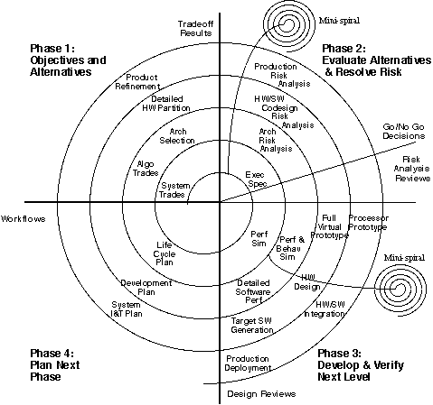
Four phases are associated with each major cycle of the spiral. In the first phase, the baseline approach and appropriate alternatives are developed to meet program objectives. During the second phase, the approaches are evaluated against the objectives and alternatives, and the risk associated with these approaches is evaluated. During the third phase, the prototype is evaluated and the next level of the product is developed. This phase results in a prototype of the design. In the fourth phase, the product is reviewed and plans for the next development stage are established. This entire process is repeated to the next level of detail by repeating each of the four phases; hierarchical application of the process results in an interactive, risk-driven approach to rapid prototyping.
In the traditional spiral model for software, each cycle might be a full set of software at some level of functionality and/or maturity, or might have critical portions of functionality prototyped (with others "stubbed" out for implementation in subsequent cycles). RASSP applies the concept of virtual prototypes, or simulated versions of the signal processor (encompassing hardware/software functionality and performance) at each cycle of the spiral. During each spiral iteration, a new virtual prototype emerges-from executable specification to high-level behavioral prototype, and then to full functional and timing versions of the design. The design then transitions into a full hardware prototype and matures into a design for full-scale production. Risk analysis and design reviews provide decision points within the cycle and enable backtracking to evaluate alternatives. New spirals are spawned to reduce high-risk elements or continue the design as planned. This model represents a more temporal overlay to the RASSP functional processes and supports concurrency (overlap) between functional disciplines.
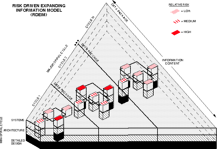
In the RASSP methodology the spiral process is applied hierarchically . Each data package may be the result of a series of mini-spirals, while also being part of the primary set of spirals within the design. As high-risk elements in the design process are indentified, "mini-spirals" can be spawned to develop critical items that are "long poles" in the design schedule. Note that this approach allows development across processes as a function of time [e.g., architecture or detailed design tasks can be performed during the early stages (systems process) for high-risk portions of the design]. The logical consequence of the process is that each successive virtual prototype has more complete functionality than its predecessor.
An expanding information view of the spiral process is shown in Figure 4 - 2. The major spiral cycles correspond to the iterations of a virtual prototype associated with the overall signal processor. The mini-spiral cycles correspond to the system, architecture, and detailed design processes associated with portions of the design and/or models (e.g. custom processor, MCM, new hardware model, new software primitive, etc.). This view corresponds to the idea that, based upon risk, pieces of the overall design may be at differing levels of maturity. At the same time, there must be a minimum maturity level achieved and data package produced for the overall signal processor to proceed from one major spiral cycle to the next. The data packages form the basis for the design reviews associated with each major spiral; these are used to drive the next iteration of the design. The data packages are inputs to (and become a subset of) the next stage of the process.
The concept of the virtual prototype as an expanding information model of the processor maps well into this paradigm. At all steps of the design, the model is characterized by four major elements-workflows, requirements, executable models, and test benches. The four elements are summarized as follows:
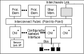
The Lockheed Martin ATL approach to implementing the Model Year Architecture is based on modular, scalable architectures that use functional standard interfaces. This approach strives to move beyond today's approach of standardizing on physical interfaces; this approach is good, but it does not go far enough to ensure technology independence. Physical interfaces encompass the lower levels of the ISO/OSI protocol hierarchy and are specific to the media and operating conditions (voltage, timing, etc.) specified by these layers. Functional interfaces provide the data-transaction-level capabilities to support communications, independent of the underlying physical technology. By standardizing on functional interfaces, we can maximize independence from technology (electrical versus optical) and specific hardware versus software (processor-based versus dedicated hardware) approaches. We will apply this approach to a number of signal processing interfaces required for RASSP, as shown in Figure 4 - 3. The RASSP team has developed a full description of this approach, which is documented in a set of specifications that can be found in the MYA application note.
The RASSP Model Year Architecture(s) must be supported by the necessary library models to facilitate trade-offs and optimizations for specific applications. Reusable hardware and software libraries facilitate growth and enhancement in direct support of the RASSP Model Year concept. The hardware and software components within the library are encapsulated by the functional wrappers required to enable efficient integration and use. We used the Model Year Architecture methodology to develop all elements for inclusion and use within the reuse libraries. This is key to attaining the 4X cycle-time improvements on RASSP. As technology advances, new architectural elements may be included in the library. Rapid insertion of a new element into an existing RASSP-generated design is the goal of the Model Year concept.
The principal benefits of hardware/software codesign are:
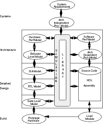
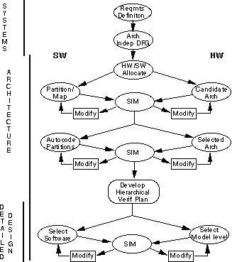
The RASSP design process is based on true hardware/software codesign and is no longer partitioned by discipline (e.g. hardware and software ), but rather by the levels of abstraction represented in the system, architecture, and detailed design processes. Figure 4 - 4 shows the RASSP methodology as a library-based process that transitions from architecture independence to architecture dependence after the systems process.
In the systems process, processing requirements are modeled in an architecture-independent manner. Processing flows are developed for each operational mode and performance timelines are allocated based upon system requirements. Since this level of design abstraction is totally architecture-independent, hardware/software codesign is not an issue.
In the architecture process, the processing flows are translated to a standard data and control flow graph description for subsequent processes. The processing described by the nodes in the data flow graph are allocated to either hardware or software as part of the definition of candidate architectures. This becomes the transition to architecture dependence. Requirements and tasks for non-DFG based software and the corresponding software are developed to the maximum extent possible.
The hardware/software allocation is analyzed via modeling of the software performance on a candidate architecture through both software and hardware performance models. For architectures selected for further consideration, hierarchical verification is performed using finer grain modeling at the ISA level and below.
During the detailed design process downloadable, executable application and test code is verified to the maximum extent possible.
Reuse library support is an important part of the overall process. The generation of both hardware and software models is supported in the overall methodology. Software models are validated using the appropriate test data. Hardware models are validated using existing validated software models. Both hardware and software models are iterated jointly throughout the design process.
During the architecture process, various simulations are performed at differing levels of detail as the design progresses. Early in the process, performance simulations are executed using high-level models of both hardware and software from the reuse library. Software is modeled as execution time equations for the various processors in the architecture. Models at the behavioral level, for both processing elements and communication elements, are used to describe the architecture. This level of performance simulation enables rapid analysis of a broad range of architectural candidates composed of various combinations of COTS processors, custom processors, and special-purpose ASICs. In addition, many approaches to partitioning the software for execution of the architecture can be rapidly evaluated. Additional detailed information regarding the role and use of simulation can be found in the following application notes:
As the architecture process progresses, each graph partition is translated into a software module for execution on a specific processor in the architecture. Functional simulation is used to verify that the generated code is consistent with the functional baseline. Performance simulation using lower-level models, which include the operating system, scheduling, and support software characteristics, provide the next level of assurance that all throughput requirements are met. Source code for non-DFG based software is developed and tested to the maximum extent possible. Finally, hierarchical architecture verification of the architecture is established using selective performance and functional simulation at the ISA and/or RTL level. The goal is to ensure that all architectural interfaces have been verified.
In the detailed design process, selective performance and full functional simulation are again performed. At this point, however, the design has progressed to where simulation at the RTL and logic-levels is most appropriate. Verification of the designs at this level is necessary before release to manufacturing. It is important to note that pieces of the design may be in different stages of the overall process based upon the risk analysis performed in each development cycle. For example, if it is obvious to the designers during systems analysis that a new custom hardware processor will be required to meet the requirements, the design of the custom processor may be accelerated while the overall signal processor design is still in the architecture process. This approach corresponds to the mini-spirals described in Section 4.1.
The Design For Testability (DFT) steps within the overall methodology enables designers to create systems that can be cost-effectively tested throughout their life cycle. Designs that adhere to the methodology are made testable on the basis of various design for testability (DFT) and built-in-self-test (BIST) techniques. The methodology covers various aspects of test and diagnosis at the chip, MCM, board and system levels, including test requirements capture; test strategy development; DFT and BIST architecture development; DFT and BIST design and insertion; test pattern generation; test pattern evaluation; and test application and control. The methodology provides the designer with a process for introducing testability requirements and constraints early in the design cycle and for addressing DFT and BIST issues hierarchically at the chip, multichip module (MCM), board, and system levels. The payback for early testability emphasis includes lower test cost throughout the life cycle of the product, reduced design cycle time, improved system quality, and enhanced system availability and maintainability.
Elaboration of the DFT steps within the overall methodology can be found in the Design For Testability application note. This application note provides additional detailed references for adopting the DFT methodology. There is a close relationship between the DFT Methodology document and the overall RASSP Methodology Document. DFT and test activities are incorporated into the overall methodology document at a high level. The DFT Methodology document describes these activities in more detail and how they interface with other design activities.
4.0 Unifying Processes and Roles in RASSP
4.1 Risk Driven Iterative Hierarchical Virtual Prototype Process (spiral model)
The goals of the RASSP program, which include rapid prototyping combined with continual process and product improvements, are more applicable to an iterative, spiral development model than the traditional waterfall development model. The spiral model was originally directed at supporting the software development process. Since the RASSP scope includes more than just software, adaptation of the model is appropriate. A view of the spiral model, as adapted for RASSP, is shown in
Figure 4 - 1.
4.2 Role of Model Year Architecture in the RASSP Methodology
To enable design reuse and minimize upgrade costs, a set of common hardware and software architecture elements is required. A key element to implement this methodology is the selection of a Model Year Architectural approach (both hardware and software) that adheres to the following principles:
The following section summarizes the approach taken for defining the concept of a Model Year Architecture. A more complete description of the technology, additional references, and actual encapsulations can be found in theModel Year Architecture (MYA) application note.
4.3 Role of Hardware/Software Codesign in the Methodology
Hardware/software codesign is the joint development and verification of hardware and software through the use of simulation and/or emulation; it begins with initial partitioning and proceeds through to design release. This section provides an overview of the hardware/software codesign definitions and technologies developed for RASSP. A more complete discussion along with specific application examples can be found in the Hardware/Software Codesign application note.
4.4 Role of Performance Modeling/Virtual Prototyping in the Methodology
Simulation is an integral part of hardware/software codesign. Figure 4 - 5 shows a top-level view of the overall simulation philosophy in the RASSP methodology. During the systems process, functional simulation is performed to establish a functional baseline for the signal processor.
4.5 Role of Design For Testability in the Methodology
![]()
![]()
![]()
![]()
Next: 5 Process
Up: Appnotes Index
Previous:3 IDEF Representation of Workflows Process