

Next:2. System Design Tools
Up: Appnotes Index
Lockheed Martin ATL's design environment implementation team has leveraged the heritage of its Engineering Process Improvement (EPI) program to combine a proven set of tools with extended capabilities for Baseline 0. Enhancements have been made in tool integration, functionality, and performance in the CAD system for Baseline 1. Intergraph will provide a framework to integrate all tools and automate process and workflow control. An updated description of the Baseline 1 tools is the focus of this document and is referred to as Baseline 2. The tools are organized according to their use within the RASSP design methodology.
A summary of the tools for systems, architecture, and detailed design (hardware and software) areas is provided in the following paragraphs. Appendix A gives a concise listing of the RASSP Baseline 2 tools. More detailed discussion of the features and use of each of these tools is given in the sections that follow. Some tools are used in more than one design area. The description of the tools will reflect the context in which they are used. Figure 1.1-1 shows an overview of all the tools used in the RASSP design process except the library tools and basic support tools such as compilers and text editors. The Design-For-Test (DFT) tools are also not shown since their use is integrated into many aspects of each design flow. The DFT tools are described in Section 1.1.4.
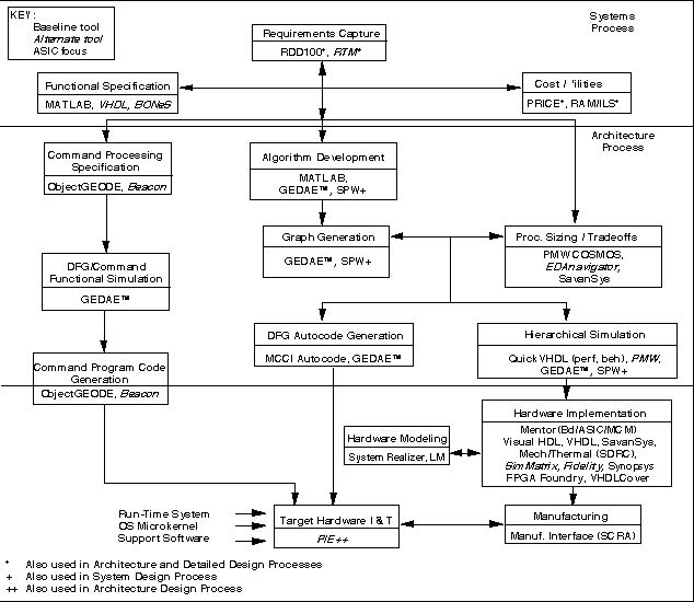
Figure 1.1-1. RASSP Design Environment-Baseline 2.
The System design tools support early development of system partitioning, test, reliability, and maintenance concepts. These tools include the following:
- RTM (Requirements and Traceability Management) from Marconi Systems is used as the requirements traceability tool throughout a program's engineering life cycle.
- RDD-100 (Requirements Driven Development) from Ascent Logic is used to capture system requirements, perform functional decomposition, model system behavior, allocate requirements to components, and generate systems engineering documentation.
- BONeS (Block Oriented Network Simulator) from Alta Group is used to perform token-based high-level system simulation, such as modeling network traffic, and is used to obtain detailed performance metrics early in the system design.
- PRICE S/M/H/HL from Lockheed Martin PRICE Systems is used for computer-aided parametric cost estimating and enables life-cycle cost analysis throughout the design process.
- RAM/ILS from MSI enables feedback on reliability, availability, maintainability, and integrated logistics to support early tradeoff analyses.
- GEDAE™ from Lockheed Martin ATL is a graphical programming and autocoding environment.
- MATLAB from Mathworks for algorithm development and numerical analysis.
- SPW from Alta Group for algorithm development.
- The Component and Library Management System (Explore (CLMS)) from Aspect is an object-oriented extension to the existing commercially-available Component Information System (CIS) product.
- Interleaf's Technical Publishing System (TPS) is the documentation production tool, which supports all levels of the design process.
The Hardware/Software Co-Design tools support the Functional Design, Architecture Selection, and Architecture Verification efforts of the Architecture Definition process. Software design tools support library development, detailed design, and source code development. These tools are:
- JRS Research Laboratories, Inc. NetSyn enables architecture selection via a design advisor.
- SavanSys from Savantage, Inc. is a tradeoff analysis tool focused on packaging and interconnection of high-performance electronic systems.
- Lockheed Martin ATL's GEDAE™ provides a workstation environment to develop applications, tools to support multiprocessor scheduling and mapping, and a run-time environment to efficiently execute on scaleable embedded processors.
- Management Sciences' RAM/ILS enables feedback on reliability, availability, maintainability, and integrated logistics.
- Alta Group's Signal Processor Worksystem (SPW) enables interactive design, simulation, and implementation of digital signal processing and communication systems.
- BDTI/UC Berkeley's Ptolemy supports multi-domain analysis of complex systems.
- RDD-100 (Requirements Driven Development) from Ascent Logic is used to capture system requirements, perform functional decomposition, model system behavior, allocate requirements to components, and generate systems engineering documentation.
- RTM (Requirements and Traceability Management) from Marconi Systems is used as the requirements traceability tool throughout a program's engineering life cycle.
- PRICE is used for computer-aided parametric cost estimating.
- SimMatrix from Precedence provides a mixed domain co-simulation environment.
- Mentor QuickVHDL provides a VHDL compilation and simulation capability.
- MATLAB is used for algorithm development and numerical analysis.
- Harris EDAnavigator from Harris Electronic Design Automation, Inc. is an alternative tool to Savantage's SavanSys.
- Performance Modeling Workbench (PMW) from Omniview and Honeywell Technology Center allows a designer to rapidly create alternative hardware/software architectures and simulate them to validate system performance.
- ObjectGEODE from VERILOG enables the generation, verification and validation of target code for the command program.
- BEACON from Applied Dynamics International (ADI) is an alternative tool to ObjectGEODE. It can be used to generate code for the command program, test vectors for unit tests as well as product documentation.
- Lucent's SPEAR supports a customizable debugging environment for multiprocessors.
- University of Oregon's PIE is an application and design evaluation environment.
- Management Communications and Control Inc.'s (MCCI) Autocoding Toolset provides autocode generation and a run-time system for graph execution control.
- GEDAE™ from Lockheed Martin ATL is a graphical programming and autcoding environment.
- Interleaf is the documentation production tool.
The RASSP Baseline 2 system provides design capabilities for hardware design in the digital and mechanical areas. The hardware design tools shown in Figure 1.1-1 have been selected and are being integrated to provide a full complement of capabilities. Mentor provides the base system for design capture, simulation, and layout.
- Mentor's FALCON Framework is used to provide a common user interface and data interchange and management capabilities. This framework is used to integrate Mentor tools and third-party applications into a single environment. The Mentor Graphics tools Design Architect, QuickVHDL, and QuickPath provide design capture, VHDL simulation, critical path analysis, functional simulation, statistical fault grading, and fault simulation, respectively. Physical design of modules is provided by the Board Station, Hybrid Station, and AutoTherm tools from Mentor Graphics.
- SimMatrix from Precedence provides a simulation backplane to support co-simulation using different simulators.
- The System Realizer Family of Modular Emulation Systems from Quickturn Design Systems provides the capability for hardware emulations.
- VHDL is generated using the graphical tool, Visual HDL, from Summit Design.
- Synopsys tools provide an environment for compiling, simulating, and synthesizing design descriptions written in VHDL.
- Programmable Logic Device and FPGA design are supported by MGC's PLD Synthesis II and NeoCAD.
- Hardware modeling capability is provided by the LM family from the Synopsys Logic Modeling Group.
- SavanSys from Savantage, Inc. is a tradeoff analysis tool focused on packaging and interconnection of high-performance electronic systems.
- Testability analysis and test database translation is accomplished through VICTORY from Teradyne and TDS from Summit, respectively.
- Managing part libraries for electrical design is accomplished through Mentor's Library Management System (LMS) software.
- Mechanical design is supported primarily by software supplied by SDRC. Their I-DEAS Master Series software provides a complete complement of mechanical design capabilities, including thermal analysis, 2D (2-dimensional) and 3D design and modeling, and finite element analysis.
- VHDLCover from VEDA Design Automation, Inc. analyzes VHDL code and determines how thoroughly the design has been tested.
- RDD-100 (Requirements Driven Development) from Ascent Logic is used to capture system requirements, perform functional decomposition, model system behavior, allocate requirements to components, and generate systems engineering documentation.
- Interleaf is the documentation production tool.
The RASSP DFT toolset is integrated into all five processes of the RASSP methodology: systems, architecture, detailed hardware and software design and integration/test. The DFT toolset interoperates with and in some cases uses functional design tools to support all phases of the product life cycle from design verification through manufacturing test and field support.
The Baseline 2 toolset is comprised of COTS tools which have been selected based upon function and inter-operability with the functional design tools.
System Process Tools
- TSTB WAVEs Test Vector generation packages from Rome Laboratory and integrated into the Mentor QuickVHDL environment are used to develop test benches in WAVEs Level II format.
- WSTA by NUWC develops functional dependency models and diagnostic strategies.
- STAT by Detex Systems, Inc. develops functional dependency models and diagnostic strategies from Mentor Design Architect netlists. A translator to the Personal Atlas Workstation Software (PAWS) by TYX Corporation facilitates the incorporation of the data into Technical Requirement Documents.
- The Test Strategy Diagram (TSD) is a graphical construct which describes how flaws and faults associated with the life cycle phases of a project are handled by a set of assigned means. It is refined throughout all phases of the design cycle.
Architecture Definition Process Tools
- TSTB WAVEs packages, SW Test Works and STAT are used during the architecture definition (selection and verification) process similar to the system process as described above.
- During Architecture Selection and Verification, BIT and fault tolerant modes/functions are captured as algorithms and flowgraphs using the normal functional design tools such as SPW by Comdisco.
- During Architecture Verification BIST insertion, testability analysis and statistical fault grading tools are used as the preliminary designs are developed. TSTB WAVEs is used to evaluate the capabilities of test equipment in measurement of required system parameters.
- ASICTEST by Logic Vision SW is used to perform preliminary test structure insertion (BIST and Boundary Scan) and to capture boundary scan descriptions of new ASICs for use in board level testability analysis tools such as VTM:TOP.
Detailed Design
- TSTB WAVEs Test Vector generation packages from Rome Laboratory and integrated into the Mentor QuickVHDL environment are used to develop test benches in WAVEs Level I format.
- STAT by Detex Systems, Inc. develops functional dependency models and diagnostic strategies from Mentor Design Architect netlists. A translator to the Personal Atlas Workstation Software (PAWS) by TYX Corporation facilitates the incorporation of the data into Technical Requirement Documents.
- ASIC Test Tool Suite by Logic Vision SW is used to perform test structure insertion (BIST and Boundary Scan), test pattern generation, fault grading and to capture boundary scan descriptions of new ASICs for use in board level testability analysis tools such as VTM:TOP.
- VTM:TOP by Mentor Graphics is used to assess the board/MCM testability based upon boundary scan and testpoint insertion.
- VICTORY by Teradyne is used to generate boundary scan test vectors for device oriented (BICT, VCT and BFT), network-oriented test (VIT and VCCT) for virtual interconnect test of components and clusters.
- LASAR will be used in conjunction with other tools to aid in developing appropriate test vectors for functional, toggle and fault tests. Its min-max simulation capability will minimize the amount of time spent debugging test programs on testers or in target systems.
- TDS by Summit is used for conversion and enhancement of simulation test vectors into tester specific formats.
- ASSET Diagnostic System is used to develop boundary scan test programs and diagnostics. During integration and test phases, ASSET is used to control, debug and isolate problems. ASSET's Scan Function Library and ScanEngine are used to generate test programs for embedded T&M controllers which control 1149.1 resources.
- Synopsys Test Compiler combines test synthesis, ATPG, fault simulation, and test management to automate DFT.
- Mentor FASTSCAN, QuickGrade, and PTM:SITE are used for scan insertion, fault grading, and test point insertion, respectively.
- SCANease is an alternative to ASSET Diagnostic System Tools.
- STARS (formerly DARTS) from MSI Systems generates a model base for a system which provides diagnostic analysis capability and repair recommendations.
- Economic Modeling Tools from Test Economic Services present a comparison of board/ASIC costs based upon entry of board/ASIC/design details with special emphasis on ATE and BScan DFT.
- IKOS Voyager is proposed to be used for fault simulation.
- The Fault Simulation Accelerator from ZYCAD may be used.
An enterprise system provides the tools and facilities for managing and providing access to the enterprise information and integrating the automated processes of an enterprise. The enterprise system for RASSP is defined as the integrated set of tools and facilities required to support the development of a signal processor prototype - design, manufacturing, test, management, procurement, etc. These tools include the following:
- DMM (Design Methodology Manager) from Intergraph is used to execute workflows (methodology) defined for a project or a high level task such as detailed design.
- DM (Document Manager) from Intergraph is used to manage product information across the enterprise.
- Explore (CLMS) from Aspect classifies, manages and cross-references all component, supplier and design data and automates the processes associated with this information, as well as the VIP Family of Component Reference Databases.
- TriTeal Enterprise Desktop (TED) from TriTeal is a graphical desktop environment that provides independence from the underlying operating system and hardware.
- MI (Manufacturing Interface) from SCRA is a standards based capability to perform design-for-manufacturing analysis and perform data translations between design and manufacturing tools.
- CommuniquŽ and Cooltalk by Insoft support a wide variety of information exchange mechanisms to support collaborative work.
- Netscape Enterprise Server from Netscape provides secure communication and browsing capabilities over the Internet.
- PGP from Viacrypt allows users to ensure that their messages are read only by intended recipients by using public key encryption.
- WorkExpert from Mentor is used to execute workflows to automate tasks.
- ProSim from KBSI is a process modeling tool used to capture processes and tasks related information. ProSim generates models that can be simulated by simulation tools such as WITNESS.
- WITNESS from AT&T is a discrete event simulation engine that provides capabilities to perform what-if analysis and evaluate alternatives based on simulation results.
- MS Project from Microsoft is used to perform project planning, scheduling, and tracking.
The high performance SPARCsystem and Series 700 workstations developed by SUN Microsystems and Hewlett Packard, respectively, are the hardware platforms that have been selected to support the RASSP design process. These hardware platforms come in a variety of configurations to support even the most demanding engineering task. The workstation type, RAM, local disk space, and server/network performance are the main factors in determining the overall performance. Each user's workstation should have sufficient RAM to support the entire tool set. A minimum of 64 MB of RAM is required (128 MB is preferred) for an individual workstation. At least 300 MB of local hard disk should be allocated for the "swap" area required for the implementation of virtual memory. An initial estimate should be taken to determine the disk size of the server or central repository. At least 10 GB will be required and, depending on the size of the project, 50 GB or more may be required.
RASSP CDRL A007 - 6/98 1-1
cad system description Baseline 2.0
Next: 2. System Design Tools
Up: Appnotes Index
Approved for Public Release; Distribution Unlimited
Dennis Basara