Next: 2 Introduction Up: Appnotes Index Previous: Appnote System Index
![]()
![]()
![]()
![]()
Next: 2 Introduction
Up: Appnotes Index
Previous: Appnote System Index
The goal of the DARPA/Tri - Service sponsored Rapid Prototyping of Application Specific Signal Processors (RASSP) program is to reduce development and manufacturing time and cost of signal processors by a factor of four. Lockheed Martin Advanced Technology Laboratories' (LM/ATL) RASSP team has developed an integrated systems engineering tool set which forms the basis for a concurrent engineering design environment. This design environment, which consists of Ascent Logic's RDD - 100, PRICE Systems parametric cost estimation models, and Management Sciences RAM - ILS tools, provides the integrated product developmentd team with cost and reliability estimation data within a systems engineering toolset. The concurrent engineering design environment is described and an example is provided which demonstrates the value of the tool integration within the design environment. This design environment enables the integrated product development team to setimate the life-cycle costs and reliability early in the design process.
The RASSP concurrent engineering environment provides the IPDT with the information they need to make decisions early, while making changes
is still easy and inexpensive. This environment will allow engineers to make decisions based not only on the current effect of a change, but on the
predicted long-term impacts. This information is essential to significantly reducing life-cycle costs.
The RASSP system definition process is a front-end engineering task in which signal processing concepts that meet customer requirements are
developed and top-level trade-offs are performed to determine the processing subsystem requirements. Although the same type of functional
decomposition and allocation is performed as in the traditional design process, several significant RASSP extensions have been developed which lead
to shorter design cycles. Emphasis is placed on understanding the life cycle impact of early design decisions in the RASSP process. Each member of
the integrated product development team participates in the system-level tradeoffs to ensure that the complete life cycle is considered during the design
process. Model year architecture concepts are used in RASSP designs to ensure that the signal processor can be easily upgraded to support its entire
life cycle. Emphasis is placed on making early design decisions so prototyping activities can begin early in the program to reduce high-risk elements.
The output of the system definition process is a set of executable specifications that have the requirements for each processing subsystem in an
executable form. The executable specifications support the RASSP concept of reuse and minimize errors due to human interpretation. Traceable
system requirements are passed via executable specifications from the system definition process to the architecture design process. As the design
progresses, the ability to meet requirements is passed back to the system-level simulations so the impact of lower-level trade-offs are analyzed.
The ATL RASSP team selected Ascent Logic Corporation's RDD-100 tool as the central tool of its integrated toolset. This tool provides
requirements analysis, functional analysis, and physical decomposition capabilities. It is an Entity, Relationship, Attribute (ERA) database tool with
a substantial graphical data entry user interface. RDD-100's database capability enables it to be the primary data storage tool for the tool set. The
ATL RASSP Team defined a set database extensions that support the IPDT through the life of a project.
The RDD-100 tool provides the IPDT with three different views of a system: a requirements view, a functional view, and a physical view. The
requirements can be related to the functions and the functions can be allocated to the physical architecture. The interrelation of these three views
enables users to automatically generate the lower specification documents from the RDD-100 database. The physical view enables cost analysis and
reliability and maintainability analyses.
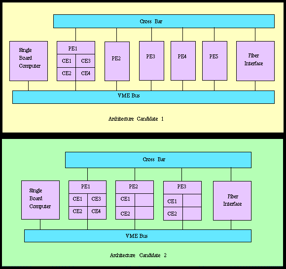
The ATL RASSP team selected a Synthetic Aperture Radar Digital Signal Processor (SAR-DSP) for a trade-off between two different architecture candidates. A preliminary functional analysis was performed to identify the hardware and software needed by each candidate architecture to satisfy the SAR functional requirements. The Candidate 1 architecture uses a mature technology. As shown in Figure 1-5, this architecture consists of a single-board computer (used as a controller), five processor elements (PE1-5), a cross bar, a fiber interface, and a VME Bus. Each processor element contains four separate computational elements (CE1-4). Also shown in Figure 1-5 is the Candidate 2 architecture. This is similar to the first, except that it uses three state-of-the-art processor elements. In addition, PE2 and PE3 contain only two compute elements rather than four.
During the development phase, the trade-off is difficult because a mature technology is less expensive per module and is lower risk, while the
state-of-the-art technology has fewer modules, is more compact, and consumes less power.
The following tasks were performed when conducting trade-offs between the candidate architectures.
Architecture 1 Architecture 2 Item QTY NHA Design Maturity QTY NHA Design Maturity Fiber Interface Assembly 1 - - 1 - - - Data IO Module 1 New Leading Edge 1 New Leading Edge - Fiber Optic Daughter Card 1 COTS Mature 1 COTS Mature - FIR Filter Daughter Card 1 NEW Leading Edge 1 NEW Leading Edge Host Interface 1 COTS Mature 1 COTS Mature Processor Element Assembly 5 - - 3 - - - Mother Board 1 COTS Leading Edge 1 COTS Leading Edge - CE Daughter Card 1 2 COTS Mature 1 or 0 COTS Mature - CE Daughter Card 2 - 1 COTS SOA Chassis 1 COTS Mature 1 COTS Mature Backplane Assembly 1 - - 1 - - - VME Backplane 1 COTS Mature 1 COTS Mature - Crossbar 1 COTS Mature 1 COTS Mature COTS : Commercial of the Shelf SOA : State of the Art QTYNHA: Quantity in Next Higher Assembly
While generating the equipment/software tree, the following information is populated in the RDD-100
database for each element:
With the tools in the concurrent design environment, this information is easily estimated, even during a proposal effort.
This system design environment quickly provides more detailed and accurate information to the IPDT, and enables them to make better informed decisions early in a system's life cycle and even in the proposal process. Since these early decisions have the largest impact on the overall life-cycle costs of a system, it is important that these decisions be based on all life-cycle costs and not just the cost of the initial development. The tools in this design environment also provide information to support detailed designers throughout the design process.
As shown in the example, it is possible to select the wrong architecture if the decision is only based on the development costs. The life-cycle costs in this example are reduced by over 20% just by understanding these costs early in the development phase. This information is critical in achieving the RASSP goal of a reducing life-cycle costs by a factor of four. The ATL RASSP team is evaluating other technologies to further reduce design-cycle times and costs on the RASSP program.
Although ATL developed the RASSP concurrent system engineering environment to work well in the signal processing domain, many of these concepts can be extended into higher-level systems.
1.0 Executive Summary
1.1 Overview
1.2 Introduction
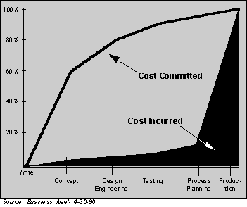
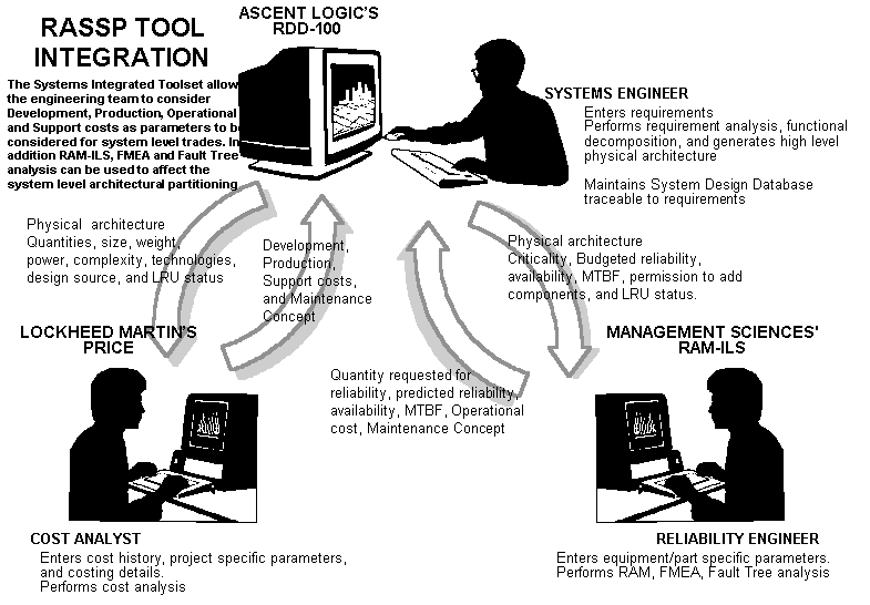
Systems enginerring decisions early in a project significantly impact schedule and cost. Decisions are typically based on the impact to the current phase of a project, rather than the project's overall life cycle. Figure 1 - 1 shows a comparison of cost incurred to cost committed for a typical project. To help the integrated product development team (PDT) make these trade-offs, the ATL RASSP team developed a concurrent engineering environment consisting of Ascent Logic Corporation's (ALC) RDD - 100 tool with PRICE Systems parametric cost estimation models and Management Sciences' (MSI) RAM - ILS tool set, as shown in Figure 1 - 2. Design information is passed among these tools in this concurrent engineering environment to provide design, cost, reliability, availability, and maintainability support to the IPDT.
1.3 RASSP Systems Engineering Process Overview
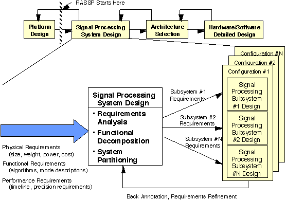
The RASSP design process consists of the signal processing system-level design, architecture selection and detailed hardware/software design, as
shown in Figure 1 - 3. The inputs to the RASSP design process are the physical, functional and performance requirements for the signal processing
system. These requirements typically are passed down from the platform system level design, which is performed prior to the signal processor design.
During the signal processing system design, the requirements are captured and analyzed, the functional behavior of the system is defined and the
requirements and functions are allocated to the major subsystems of the signal processor. Hardware/software co-design activities are performed during
the architecture selection process and a virtual prototype of the system is developed. Once the processing architectures are determined, the hardware
and software are developed and integrated during the detailed design process. Note that these processes are iterative in nature and that feedback between
the processes is used whenever required. The focus of this section of the application note is to present an overview of the RASSP systems
engineering process.
1.4 Design Environment Overview
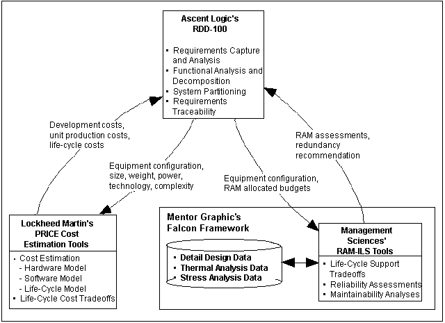
The RASSP concurrent engineering environment consists of ALC's RDD-100, PRICE System's cost estimating tools and MSI's RAM-ILS toolset,
as shown in Figure 1 - 4. The capabilities for each individual tool and for the integrated toolset are described next.
1.4.1 RDD-100
The ATL RASSP team selected Ascent Logic Corporation's RDD-100 tool as the central tool of its integrated toolset. This tool provides
requirements analysis, functional analysis, and physical decomposition capabilities. It is an Entity, Relationship, Attribute (ERA) database tool with
a substantial graphical data entry user interface. RDD-100's database capability enables it to be the primary data storage tool for the tool set. The
ATL RASSP Team defined a set database extensions that support the IPDT through the life of a project.
1.4.2 PRICE Systems Cost Estimation Models
The ATL RASSP team selected Lockheed Martin PRICE Systems' parametric cost estimation models as the cost analysis tool. These models were
originally intended to be used by a cost analyst. PRICE Systems modified them to allow access to the PRICE models through parameters contained
within the RDD-100 database and to provide costing information back to this database. The PRICE Systems' tools include a set of four parametric
cost estimation models, each with a different specialty areas. Three of the models focus on hardware costing and the fourth model focuses on software
costing. These models are summarized below:
The PRICE models are based on historical models and can be calibrated to match any company's process.
1.4.3 Reliability, Availability, Maintainability: Integrated Logistics Support (RAM-ILS)
Management Sciences' Inc. RAM-ILS tools calculate reliability, maintainability, and availability of a system. This tool set performs mean time between failure (MTBF) and availability calculations using several methods, including Mil-Hdbk-217 and BelCore. If the system doesn't meet the MTBF requirements, RAM-ILS will perform a cost driven trade-off and recommend where redundancy can be added to effectively meet the system MTBF requirement. RAM-ILS is integrated with the Mentor Falcon Framework, which allows it to access the detailed design database to continually improve its estimates as the detailed design progresses.
1.4.4 Integrated Tools
As a part of the RASSP program, RDD-100, PRICE and RAM-ILS have been integrated so design information can be passed among the tools when performing system, costing and reliability analyses. It is through the use of the integrated tools that provides the capabilities needed by the IPDT. The approach used to integrate these tools within the concurrent engineering design environment is to pass data normally resident within one tool to another tool if that data can be used for analyses within the receiving tool. There has been no attempt to build a graphical user interface within any tool for another tool. All data exchanges for these tools are file based.
1.5 Integrated Tools
The following example problem shows how the concurrent engineering environment is applied to a trade-off study.
Each of these tasks are described below.
1.5.1 Requirements Capture and Analysis
The initial requirements capture and most of the requirements analysis are essentially identical for both candidate architectures. The originating requirements came from a Technical Description Document. The team reworded and reordered these requirements to create a specification for the signal processor. After completing the initial requirements decomposition, the team performed a functional analysis.
1.5.2 Functional Analysis
The functional analysis for both candidate architectures is essentially the same since both architectures are functionally equivalent. The functions are
decomposed down to the point where each leaf-level function is allocated to a hardware or software element. At this point, some information about
the hardware/software partition may help minimize future changes to the functional decomposition.
1.5.3 Physical Decomposition
The physical decomposition is the only information required to perform cost and reliability analysis. The team developed an equipment/software tree
for both candidates that is essentially identical. The primary difference is in the quantities of processor element assemblies. Table 1 - 1 shows an
element tree for each of the candidates.
1.5.4 Preliminary Cost Calculation
The team calculated the preliminary cost using the PRICE H, PRICE HL and PRICE S tools. The PRICE tool was configured previously with
company-specific calibrations and a deployment environment and scenario. The deployment scenario included two prototypes and 500 production
units over a 20-year mission, with 20 organization sites and one depot maintenance site. (An export to PRICE was run from the RDD-100 tool
and an import was then run in the PRICE tools.) Table 1-2 shows the calculated costs for Candidate 1. This data was exported from the PRICE
tools back to RDD-100. The whole cost analysis and back population is done in less than 1/2 hour. This process allows the IPDT to quickly
assess several similar architectures.
Cost Cycle Predicted Cost ($M) Development Cost 1.9 Production Cost 95.8 Life Cycle Support Cost 36.9 Total Cost 134.6 1.5.5 Preliminary Reliability Calculation
After completing the first costing, an export is performed from RDD-100 to the RAM-ILS tool set. This tool set then calculates the overall MTBCF (mean time between critical failure) and compares it to the budgeted value. In this case, Candidate 1 only achieved a 2069-hour MTBCF for a 2400-hour requirement. Based on a cost trade-off performed within the RAM-ILS tool, this tool recommends that the requirement can be met if a redundant fiber interface is added. RAM-ILS generates the back population results for transfer into the RDD-100 tool. Each component has an attribute "quantity requested for RMA" that indicates where the RAM-ILS tool suggests redundancy. Note that this is just a recommendation from the RAM-ILS tool; systems engineers must determine the feasibility of this recommendation. All the RMA calculations are performed against the original system. If the users believe that this suggestion is proper and feasible given the hardware and software configuration, they change the "quantity in next higher level assembly" within the RDD-100 tool and run the RAM-ILS tool on the new configuration. The final MTBCF for Candidate 1 with the recommended redundancy is 2607 hours.
1.5.6 Cost Updates
At this point, the architecture has changed and more accurate MTBF numbers were available in the database. The team ran the PRICE tools a second time, which provided a more accurate cost assessment, as shown in Table 1 - 3.
Cost Cycle Predicted Cost ($M) Development Cost 2.0 Production Cost 101.0 Life Cycle Support Cost 39.6 Total Cost 142.5 1.5.7 Architecture Trade-Off
The team performed similar cost analysis and RMA analysis for Candidate 2. The costing and reliability results for both candidates are shown in
Table 1-4. During a typical project, the development costs are the primary criteria used to select the best architecture. Therefore, the life-cycle
costs would not be minimized. With the concurrent engineering design environment, the IPDT can pick the most cost-effective solution based on
the total life-cycle costs. In the past, Candidate 1 would typically have been selected because there was no easy process to determine life-cycle
costs. It is clear from this example that Candidate 2 is the better solution because it is less expensive and more reliable.
Cost Type Candidate 1 ($K) Candidate 2 ($K) Development Cost 2.0 2.1 Production Cost 101.0 89.1 Life Cycle Support Cost 39.6 29.8 Total Cost 142.5 113.0 MTBCF 2607 hours (Redundancy Required) 3296 hours (No Redundancy) 1.6 Summary
The ATL RASSP team has developed a concurrent engineering environment consisting of three existing computer tools (RDD-100, Price Cost Estimating, and RAM-ILS).
![]()
![]()
![]()
![]()
Next: 2 Introduction
Up: Appnotes Index
Previous:Appnote SYSTEM Index