Digital Design Laboratory
Johnson Counter
(Use of Flip-Flops and design of counters)
Purpose:
The purpose of this lab is:
-
1. To get familiar with the use of flip-flops
-
2. To design an up/down Johnson counter using D flip-flops
-
3. To implement the counter on a FPGA or CPLD
-
4. To experimentally check the operation of the counter
Problem Statement:
The goal is to design a Johnson counter that can count up or down, depending
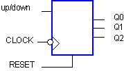
on the setting of a control input UP/DOWN. The block diagram of the counter
is given in Figure 1.

Figure 1: Symbol of the 3-bit up/down Johnson counter.
The counter has an asynchronous reset (or clear) input which brings
the outputs to 0 as soon as the RESET signal is asserted. The counter counts
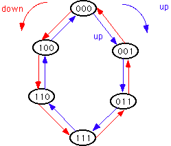
at the negative edge of the clock. When the UP input is high, the counter
counts in one direction and when UP is low, it counts in the other direction,
as shown in the state diagram of Figure 2.

Figure 2: State diagram of the UP/DOWN Johnson counter.
Pre-lab Assignment:
-
Review the design procedure in your class notes or the textbook
for counters.
-
Use the standard counter design process to design this up/down Johnson
counter with D flip-flops (do not use the state editor). Notice that
the asynchronous reset will bring the counter in a known and allowed state
(000).
- Give the State transistion table (hint: consider the UP signal as an
input together with the three present states). You should make use of don't
cares (for unused states) in order to reduce the amount of logic required
for the flip-flop inputs.
-
Draw the K-maps for the three D inputs: DA, DB and
DC.
-
Give the logic expression and logic diagram of each function DA,
DB and DC. Can you see similarities between these
three functions?
-
This state machine will have unused states. In case you get stuck
into one of these unused states,e.g. state (010), what will the the
next two states be, assuming that you do not use the reset switch to get
back into the starting state: (010) -> (???) -> (???). Is this a self-starting
counter?
- Based on the similarities (or symmetries) of the three functions DA,
DB and DC, can you extend the design to more
bits? When drawing the schematic of the counter, you will easily see how
to extend the counter from a 3-bit to a 4-bit counter. Give the expressions
of DA, DB, DC, and DD
for a 4-bit Johnson counter. Also draw the schematic in your notebook.
- On-line pre-lab Questions. Submit your answers to the above questions
online using Blackboard.
-
Sketch the full diagram of the 4-bit Johnson counter (logic and
FF) using negative edge triggered D flip-flops with an asynchronous reset.
Assume that the D flip-flops are available as building blocks (you do not
have to design your own flip-flop).
-
Divide by 8 circuit. You will display the state of the counter the
7-segment LEDs. In order to be able to read the displayed numbers
you need to slow down the clock signal by a factor of 8. Design a divide
by 8 circuit, using D or T (made from D flip-flops) and write it down in
your lab notebook.
In-lab assignment:
A. Parts and Equipment:
-
1. PC
-
2. Xilinx Foundation Tools F2.1i
-
3. Xilinx FPGA Demoboard (with XChecker cable and power cable),
XS40 or XS95 boards.
B. Experiments
The goal is to enter the schematic of the Johnson counter, to simulate,
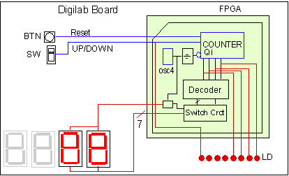
implement and test the counter on the FPGA demoboard. Figure 3 schematically
shows the test set up on the demoboard.

(a)

b.
c.
d.
Figure 3: Schematic test set up of the counter using the (a)
Digilab board, (b) FPGA demoboard, (c) XS40 or (d) the CPLD
XS95 board
-
Create a new project in the Schematic Flow mode and name it MYCOUNT.
Place this project in your folder (C:\users\your_name) on the C:drive
.
-
Create the schematic of the Johnson counter according to the design
of the pre-lab. Keep the schematic as simple as possible. If you can use
a macro for the logic for the D inputs, you should do so to keep the schematic
from being cluttered with too many gates and wires.
-
For the D flip-flop, use one of the flip-flops which are available in the
Xilinx library (SC Symbols window). The name of D flip-flops starts
with FD. For instance, FDC is a positive edge triggered D flip-flop with
a clear (reset) input; FDC_1 is a negative edge triggered D flip-flop with
a clear input. If you are not sure, select the flip-flop and a brief description
of the flip-flop will appear at the bottom of the SC Symbol window.
-
If you build a 4-bit counter instead of a 3-bit counter you will get 10
bonus points.
-
You will need a clock to advance the counter. There are several possibilities.
One is to use an external function generator such as the HP 33120A waveform
generator. Another option is to use a debounced push button switch and
manually advance the clock. A third option is to use the clock generator
that is available on the FPGA chip (not on the CPLDs). In case you are
working with a FPGA, you will be using the last option. Place the symbol
(OSC4) for the oscillator on the schematic. This oscillator has four outputs
corresponding to four different clock frequencies. Select the lowest frequency
output (i.e. the 15 Hz output). This clock is still too fast to see the
display. Divide the clock signal by 8 and use the slow clock to connect
to clock inputs of the D flip-flops.
-
The way you apply the inputs (UP and RESET) and display the outputs of
the counter will depend on the type of board you are using.
-
For the Digilab board:
-
The output of the counter will be displayed in two ways. First, the state
of each flip-flop will be shown on the individual LEDs, LD (Fig. 3a). Second,
you will also display the numerical value of the counter on two 7-segment
displays (counting from 0, 1, 3, 7, 15...,0, etc in the UP mode and 0,
8, 12,...0, etc in the DOWN mode). Remember that the LED segments of the
displays are active-low. You will need to design the decoder for
these two 7-segment displays. In addition, you need also to include a switching
circuit that allows you to use the two 7-seven segment displays.
-
The schematic should include the input and output pads and buffers for
each input and output. The UP/DOWN control should be connected to one of
the input general purpose slide switches SW
on
the Digilab board (see Figure 3a). The reset button needs to be connected
to one of the push-button
switches BTN.
-
For easy use of the counter, you should also indicate on one of the bar
LEDs when the UP/DOWN signal is asserted (1) or not (0) as is shown in
Figure 3a. The LED should be ON when the counter counts upwards (i.e. UP=1).
An alternative way is to use a third 7-segement that displays a "u"
for UP and a "d" for DOWN.
-
For the FPGA demoboard:
-
The output of the counter will be displayed in two ways. First, the state
of each flip-flop will be shown on the LED bar display (Fig. 3a). Second,
you will also display the numerical value of the counter on the 7-segment
display (counting from 0, 1, 3, 7, ..., 0, etc in the UP mode and 0, 8,
12,...0, etc in the DOWN mode in case of a 4-bit counter). Remember that
the LEDs are active-low. You will need to design the decoder for the 7-segment
display.
-
The schematic should include the input and output pads and buffers for
each input and output. The UP/DOWN control and RESET signals should be
connected to one of the input switches SW3
on
the demoboard (see Figure 3b).
-
For easy use of the counter, you should also indicate on one of the bar
LEDs when the UP/DOWN signal is asserted (1) or not (0) as is shown in
Figure 3. The LED should be ON when the counter counts upwards (i.e. UP=1).
-
For the XS40 board:
-
The state of the counter will be displayed on the 7-segment
LED display. If you design a 4-bit counter, the display should
show the numbers 0, 1, 2, ... 7, 0, etc when counting UP and 0, 7, 6, ...,
0, etc, when counting DOWN. Design the decoder for the display.
-
The UP/DOWN and RESET signals can be applied through the parallel
port.(Figure 3c).
-
For the XS95 CPLD board:
-
The state of the counter will be displayed on the 7-segment
LED display. If you design a 4-bit counter, the display should show
the numbers 0, 1, 2, ... 7, 0, etc when counting UP and 0, 7, 6, ..., 0,
etc, when counting DOWN. Design the decoder for the display.
-
The UP/DOWN and RESET signals can be applied through the parallel
port.(Figure 3d). The clock signal also needs to be applied. This can
be done through the parallel port (you can use the ports D0 or D1
which have Schmitt triggers located at pin 2 or 3). Alternatively,
you can use one of the available I/O ports on the CPLD to apply an external
clock from a function generator.
-
When finished with the top-level schematic, label all the nets between
the PADs and buffers. Also label some of the internal nets including the
CLOCK line (output of the oscillator OSC4). These names have to be unique
and
will be used by the simulator and also in the user constraint file. A convenient
way to label inputs and outputs of flip-flops is to use as input the flip-flop
symbol (e.g. D for a D-FF) with a subcript the name of the flip flop (e.g.
DA), while the name of the output of the flip-flop is Q with the same subscript
as the input (e.g. QA or A for short).
-
You can assign pin numbers to all the input and output signals on the schematic
or later on using the constraint editor.
-
Functional simulation of the Johnson counter. Check that the counter
works properly.
-
Do a functional simulation. The most convenient way to run the simulation
is to assign keyboard buttons to each input signal (e.g. assign the UP
signal to the "u" key, the RESET signal to the "r" key, etc.) instead of
using the binary counter output Bc. This allows you to toggle the value
on the input signals by pressing the respective key. When you click then
the STEP button in the Simulator Window, a simulation step will be performed
for the current inputs. The OSC4 does not oscillate when doing the simulation.
You will need to assign a stimulus signal to the clock line (e.g. assign
the "c" key to it).
-
When you have verified that the counter works properly, take a screen capture
of the waveform. You should catpture only the waveform that contains
the proper output to verify that the circuit works properly.
-
Implement your design on one of the FPGA boards.
-
Run the implementation.
-
Check the reports and write the results in your lab notebook:
-
Check the reports and write the results in your lab notebook:
-
Check the Map Report for the device utilization and the equivalent gate
count. Check if logic has been removed during the mapping step.
-
Check the Post Layout Timing Report. Find the maximum path delay
and net delay. What is the maximum frequency at which you can run
your counter?
-
When the implementation is successful, do a timing
simulation and check the delays in each stage (from negative clock
edge to the actual flip-flop outputs).
-
If you haven't specified the pin location on the schematic, you can do
it now by using the constraint
editor. Read the section on the constraint editor carefully. Check
the description of the boards to find out the pin numbers.
-
Re-run the implementation using the right user constraint file.
-
Configure your
design into the FPGA or CPLD.
-
Test your design by observing the LEDs. Have the lab instructor
check it out.
Hand-in
You must hand in a lab report that contains the following:
1. Course Title, Lab no, Lab title, your name and date.
2. Section on the Pre-lab with answers to all questions, unless they
have been submitted online.
3. Section on the lab experiment:
a. Brief description of the lab experiment including the goals.
b. Screen capture of the schematics and copy of the HDL source code
of each macro including the divider.
c. Results of the functional and timing simulation (screen capture,
indicating delays).
d. Summary of the Map (device utilization) and Timing Reports (delays,
max. frequency)
4. Conclusion and discussion.
The lab report is an important part of the laboratory. Write it carefully,
be clear and well organized. It is the only way to convey that you did
a great job in the lab. It is preferred (but not necessary) that you type
the lab report.
References:
-
M. Mano and C. Kime, "Logic and Computer Design Fundamentals", 2nd edition,
Prentice Hall, Upper Saddle River, 2001.
-
R. Katz, "Contemporary Logic Design", Benjamin/Cummings Publ., Reading,
MA, 1994.
-
J. F. Wakerly, "Digital Design," 3rd Edition, Prentice Hall,
Upper Saddle River, NJ, 2000.
-
A. Dewey, "Analysis and Design of Digital Systems with VHDL," PWS Publishing
Company, Boston, 1997.
Go to the Xilinx
Foundation Tutorial
Copyright 2000, Jan Van der
Spiegel; Created October 31, 1997; Updated October 25, 2001.
