![]()
작성일: 2007.12.21


| By Denny Steele, Altera | December 13, 2007 |
Traditionally, the term "low power" and "programmable logic" have not been used in the same context. However, the advent of zero-power CPLDs transformed the discussion, as this technology brings many advantages of programmable logic to designers of low-power electronic products. In addition to the demonstrated ability of a CPLD to excel in general purpose applications, zero-power CPLDs can reduce overall power consumption in portable products.
General-purpose CPLD applications
A first group of applications represents functions for which CPLDs
excel. While these are not specific to reducing power, nevertheless,
using a low-power CPLD to enable these applications has a positive
net effect on power consumption. For example, a common CPLD function
is consolidating discrete logic. This saves space on the PCB,
reduces bill of materials (BOM) costs, and lowers the overall power
consumption. The following sections discuss some of these common
general-purpose applications.
Power Sequencing
In many products, the power up order of various devices is
important, making power sequencing a critical function. A CPLD comes
alive within microseconds of the system power-on, making it an
excellent choice for controlling the power-up order of various
devices in the system, including a microprocessor or microcontroller
(See Figure 1). This power sequencing is just one of many system
functions that low-power CPLDs can accomplish. Obtaining the highest
value from programmable logic comes from incorporating several
functions into one device.
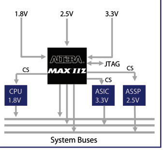
Figure 1. Power Sequencing Using a CPLD
Voltage-Level Translation
Many products require the use of logic devices of varying voltages.
To support multi-voltage applications, designers frequently need to
connect devices of differing voltage levels. CPLDs have a large
number of I/Os which are grouped into multiple banks. Each I/O bank
is, in turn, assigned a unique voltage source. Thus, creating a
voltage-level shifter is merely a matter of grouping all the I/Os of
one voltage in one bank and connecting the associated voltage
reference to the power rail needed for those I/Os (See Figure 2).
While it is useful to be able to accomplish level shifting using a
CPLD, an even greater advantage is derived from the power of
programmability combined with the level shifting. For example, if an
application calls for an LCD display that is not supported by the
host processor and is not at the same voltage level, a CPLD could be
used to provide voltage-level shifted timing control between the
host processor and an LCD display.
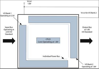
Figure 2. Using a CPLD to Perform Voltage-Level Shifting
General Purpose I/O Pin Expansion
There are many other cases where a CPLD makes an excellent
companion to a microcontroller, application specific standard
product (ASSP), or application specific integrated circuit (ASIC).
For example, in a common application known as general purpose I/O
(GPIO) pin expansion, designers combine the programming capabilities
of a small, inexpensive microcontroller with the GPIO resources of a
CPLD. The CPLD builds a set of internal registers that can be
accessed by the microcontroller through any available serial port
such as I2C or SPI (See Figure 3), allowing the
microcontroller to use the existing serial port to expand the total
I/O count.
CPLD-expanded I/Os can also be used to accomplish voltage level shifting, thus increasing the utility of the CPLD.
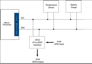
Figure 3. GPIO Pin Expansion
While the example given uses a microcontroller, it is equally applicable to an ASSP or ASIC. For example, many designers have discovered that a small ASIC driving a CPLD through a serial interface is a less expensive solution than producing one large ASIC with the same I/O capabilities.
Interface Bridging
Portable application designers often find a need to connect devices
with differing I/O interfaces. This function is referred to as
bridging because the CPLD is used to form a bridge between the
dissimilar interfaces. Figure 4 illustrates the use of a CPLD to
bridge between two differing serial interfaces: I2C and
SPI. This design can be employed and use approximately 43% of the
available logic and six I/O pins.
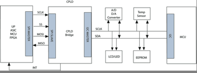
Figure 4. I2C-to-SPI Interface Using a CPLD
Figure 5 shows a host processor interface to an SPI master as an example of using a CPLD to implement a serial-to-parallel interface. This example creates a host processor bus interface and a complete SPI master and can be implemented in this CPLD using approximately 30% of the available logic and 25 I/O pins.
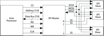
Figure 5. Host Processor-to-SPI Interface Using a CPLD
In Figure 6, a CPLD is used to bridge between two different parallel interfaces. This design example implements a PXA310 host processor bus interface to a Compact FLASH+ device. It can be implemented in a CPLD using approximately 17% of available logic and 59 I/O pins.
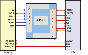
Figure 6. Host Processor to CF+ Interface Using a CPLD
Applications for Reducing Power Consumption
The previous applications demonstrate the use of a low-power CPLD
to accomplish many of the functions common in portable applications.
The next group of applications illustrates specific ways to use the
unique features of a zero-power CPLD to reduce the power consumption
in portable applications.
Self Power-Down and Power-Up
This CPLD provides an example of a zero-power CPLD with ultra-low
standby power consumption. This device consumes just 29 μA in
standby. However, in order to achieve the absolute lowest power, it
would be ideal if a device consumed no power when it is not being
used. Surprisingly, this is actually achievable since, unlike
traditional macrocell-based CPLDs, the device contains an internal
oscillator that can be used to build an auto-power-down capability.
The operation is simple; all of the inputs to the CPLD are used to control a counter. If any input is active, the counter is held on reset. When all of the inputs go inactive, the counter counts until a user-defined length of time has passed. If during this time all of the inputs are still inactive, a signal is sent to disable a metal-oxide-semiconductor field-effect transistor (MOSFET), which shuts off power to the device. When any input goes active again, the internal counter is reset, power is applied, and the CPLD powers up (See Figure 7).
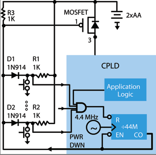
Figure 7. Auto-Power-Down and Auto-Power-Up When Inputs are
Inactive
Powering Up with Multiple Input Possibilities
The ability of a CPLD to easily monitor its inputs and do a
self-stop or self-start has direct application to reducing power
consumption in portable applications. In many portable products,
power-up is accomplished by the push of a power-up button. If the
product is idle for some period of time, a shut down or standby mode
is invoked to conserve battery life. At this point, many portable
designers would like any user action to re-activate the product, for
example, opening the cover, pushing any key, inserting a memory
card, etc. (See Figure 8). However, many power management designs
only allow one control input. In this case, the CPLD can be used to
monitor the inputs. When the product is idle for a
designer-determined period of time, the CPLD issues a power-off
signal to the power management logic. Then when any input goes
active, the CPLD powers up and issues a system power-up signal to
the power management logic.
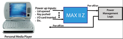
Figure 8. Using a CPLD to Start and Stop System Power Based on
Input Activity
Using a CPLD as a Power-Reducing Coprocessor
There are many system functions that can be off-loaded from a
large, power-hungry host system processor to a small power-frugal
CPLD. One type consists of the many system "housekeeping" functions
that must be done on a periodic basis. In the following examples,
the system processor can remain in a power-savings mode, while the
low-power CPLD uses its internal oscillator to periodically execute
the task. If desired, the internal oscillator of the CPLD can be
calibrated to an external oscillator. After calibration, the
external oscillator can be powered off for even more power savings
(See Figure 9).
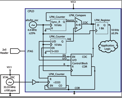
Figure 9. Calibrating the CPLD's Internal Oscillator to an
External Source
Using a CPLD to build a low power media coprocessor provides another opportunity for significant power savings. In this application, instead of having the host processor stream the media file to a codec, the host processor is put to sleep and the CPLD is used. Typically, the power consumption of a CPLD doing this function is in the low micro-amps, compared to the milliamps required by the host processor. This power savings directly translates in longer battery life.
Summary
Traditionally, low-power portable product designers have not been
able to take advantage of the many benefits that programmable logic
has to offer. However, zero-power CPLDs with standby current in the
low micro-amps range now make these programmable devices a viable
option for product designers focusing on low power applications.
Showing examples of using CPLDs to implement general-purpose system functions, this article illustrates the unique ability to build self-stopping and self-starting circuits in CPLDs. This capability is then applied to show specific design methodologies for reducing power consumption in portable applications. In addition, this article shows how to offload tasks such as periodic system monitoring and media streaming from the host processor to a lower power CPLD coprocessor. As a result of zero-power CPLDs, portable electronics product designers now have an even greater ability to create innovative, low-power, feature-rich products.
About the Author
Denny Steele, senior marketing manager, low cost
products, joined Altera in May 2006 as a Senior Marketing Manager.
Steele has over twenty years of industry experience, specializing in
the use of programmable logic in high volume, low power, consumer
electronic products. Before joining Altera, he held applications
engineering and marketing positions at Philips Semiconductors and
Xilinx Inc.He can be reached at: dsteele@altera.com
![]()
![]() Send to a colleague |
Send to a colleague | ![]() Print this document
Print this document